Passive Splitters, Combiners & Couplers · Volume 5
DIY Build, Measurement and Buys
A microstrip Wilkinson whose board is drawn to scale rather than asserted, the HF four-way transformer tree, the three network-analyser sweeps and the port that has to be terminated in all of them, and a commercial survey in which every checked frequency range turned out to be the part number read as a specification
5.1 About this volume
Four volumes of theory arrive here: at a board, a core, a network analyser and a catalogue. This is where the dive either produces something a reader can build and buy, or does not.
The seed chapter’s two builds and its commercial tables are the part of it that fared worst under checking, and in a specific and instructive way. The physics sections contained errors of mechanism behind conclusions that were broadly right. The build and buy sections contain errors of fact — a board that cannot hold its own design, a bandwidth goal unreachable by the topology specified, a cost total that disagrees with its own parts list, and four product rows whose frequency ranges are, on inspection, the part numbers read as specifications.
Three results lead.
The specified PCB is nowhere near large enough for the design it carries — the branch line is 4.7 times the board’s longest side — and the paragraph containing the error also contains the correct calculation and then instructs the reader to ignore it. §2 lays the three inconsistent figures side by side.
Every commercial frequency range that could be checked was wrong, and three of the four are explicable by the same mechanism: the digits in the part number were read as a band. §6 shows the pattern.
And the verification procedure omits the one instruction that matters. §5 finds that none of the seed’s three sweeps says to terminate the unused port — which, by Vol 2 §4, is the single action that keeps the network in the mode all the other numbers assume.
5.2 The specified board cannot hold the specified design
The seed’s §14.2 reads, in sequence:
Length: λ/4 at center frequency (e.g., 75 mm at 1 GHz; 750 mm at 100 MHz)
For a 100 MHz design, the λ/4 lines are 75 mm long — fits comfortably on a 90 × 60 mm PCB.
For a 1 GHz design, the λ/4 lines are 75 mm long — same length! (because the velocity factor in FR-4 dielectric gives λ at 1 GHz of ~150 mm, with λ/4 being 37.5 mm — but typical Wilkinson uses 75 mm at 1 GHz for the 100 MHz – 1 GHz coverage with one design)
Three different claims about the same quantity, in three consecutive sentences.
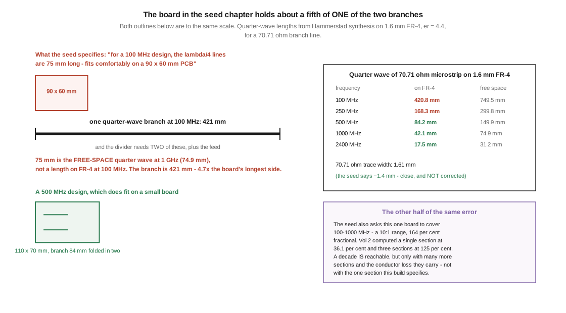
The first is correct, and should be confirmed: 75 mm and 750 mm are the free-space quarter waves at 1 GHz and 100 MHz, to better than a per cent. The second says a 100 MHz quarter wave is 75 mm, contradicting the line immediately above it by a factor of ten. The third asserts the same 75 mm for 1 GHz, then parenthetically performs the dielectric calculation the design actually needs — and having got a different answer, overrides it.
Synthesising the line properly settles it. For a 70.71 Ω branch on 1.6 mm FR-4 with εr = 4.4, the Hammerstad model gives a trace 1.605 mm wide with an effective permittivity of 3.172, so the quarter wave is:
Table 1 — Synthesising the line properly settles it. For a 70.71 Ω branch on 1.6 mm FR-4 with εr = 4.4, the Hammerstad model gives a trace 1.605 mm wide with an effective permittivity of 3.172, so the quarter wave is
| frequency | quarter wave on FR-4 | free space |
|---|---|---|
| 100 MHz | 421.0 mm | 749.5 mm |
| 250 MHz | 168.4 mm | 299.8 mm |
| 500 MHz | 84.2 mm | 149.9 mm |
| 1 GHz | 42.1 mm | 74.9 mm |
| 2.4 GHz | 17.5 mm | 31.2 mm |
A 100 MHz microstrip Wilkinson needs two branches of 421 mm each. It does not fit comfortably on a 90 × 60 mm board; it does not fit on it at all. A single branch is 4.7 times the board’s longest side, and the divider needs two of them plus the feed, so the copper to be accommodated is more than 840 mm. The lead figure draws the board and the branch to the same scale, so the comparison needs no arithmetic.
Two details are worth handling carefully, because over-correction is a named failure mode here.
The seed’s parenthetical is nearly right and is not the error. Its “λ at 1 GHz of ~150 mm, with λ/4 being 37.5 mm” implies an effective permittivity of 4, against the 3.172 the synthesis gives for this particular narrow trace; 37.5 mm against 42.1 mm is about 11 % low. That is a reasonable engineering approximation that went wrong only by using the substrate’s bulk permittivity instead of the line’s effective one. The fault is not the calculation; it is the decision to discard it.
And the trace width is right. The seed says “~1.4 mm” for 70.71 Ω on 1.6 mm FR-4; synthesis gives 1.605 mm. That is 13 % apart, well inside the spread produced by different εr assumptions for FR-4, which is a genuinely variable material. Confirmed, not corrected.
There is a second, independent problem with the same build. Its title promises 100–1000 MHz, a 10:1 range — 164 % fractional bandwidth. Vol 2 computed a single-section Wilkinson at 36.1 % and a three-section design at 125 %, both at 20 dB. A decade is reachable with a multi-section design, but it needs considerably more than the three sections Vol 2 examined, and every added section brings the conductor loss §4 of that volume attributed correctly. The seed proposes to cover a decade with one section. The geometry is impossible and the goal is unreachable, and the two faults are unrelated.
5.3 A Wilkinson that does fit
The corrected build targets 500 MHz, where the quarter wave is 84.2 mm and the whole divider fits on a board a fabricator will make for a few dollars. At 20 dB the single section covers 0.819 to 1.180 of the design frequency, which is 410 to 590 MHz — enough for the 70 cm amateur band, most ISM work at 433 MHz, and general bench use.
5.3.1 Bill of materials
Table 2 — 3.1 Bill of materials
| item | specification | note |
|---|---|---|
| PCB | 1.6 mm FR-4, 1 oz copper, 110 × 70 mm | any low-cost fabricator |
| branch lines | 70.71 Ω microstrip, 1.61 mm wide, 84.2 mm long, two of them | folded if the board is to be smaller |
| isolation resistor | 100 Ω, 1206 thin-film, 1 % | thin-film rather than thick-film: lower parasitic inductance |
| connectors | 3 × SMA edge-mount, 50 Ω | one input, two outputs |
| ground | continuous plane on the reverse, via-stitched along both branches | the plane is the other half of every microstrip line |
The seed’s own BOM — FR-4 or Rogers, a 100 Ω 1206 resistor, three SMA edge-mounts, about $22 in parts — is sound and is kept. Only the dimensions change.
5.3.2 Construction notes that matter
The ground plane is a circuit element, not a convenience. Microstrip impedance is defined between the trace and the plane beneath it; a gap or a slot in that plane under a branch line changes the line’s impedance locally and will show up as a bump in the input match. Keep the plane unbroken under both branches.
Keep the two branches symmetric. Vol 2 §8 established that isolation in any of these structures fails through imbalance. Two branches of slightly different length or width put an even-mode signal into the odd-mode path, and the isolation floor is set by that asymmetry rather than by anything about the resistor. Mirror the layout exactly.
Mount the resistor across the two output feedpoints, with the shortest possible leads. At 500 MHz a millimetre of lead is about 1 nH, which is 3 Ω of reactance — small against 100 Ω, but it grows as the square of frequency in its effect on isolation. This is why chip resistors, not leaded ones.
Fold the branches if the board must be smaller. A meandered quarter wave behaves as a straight one provided the folds are gentle and adjacent runs are kept at least three trace widths apart, so that the line does not couple to itself.
5.4 The HF four-way, which is a tree
Below VHF the quarter wave is impractical — 421 mm at 100 MHz, and metres by the time the HF bands are reached — so the HF splitter is built from transmission-line transformers on ferrite, exactly as Vol 2 §8 describes. The seed’s second build is such a device, and its architecture is correct: a two-stage corporate tree, input to two, then each of those to two again, giving four outputs.
That is worth stating plainly because Vol 2 §7 found the chapter’s N-way table implies a star instead. The build is the half that is right. Its parts list is also internally consistent with a tree: it calls for three 100 Ω bridging resistors, which is exactly what a two-stage binary tree needs — one in the first stage, two in the second. A star would need a different count. The chapter knew the correct architecture and tabulated a different one.
Two numbers in the build need attention.
The inherent loss is 6.02 dB, and the chapter’s ~7 dB per output is a fair figure with about 1 dB of excess. Confirmed; a four-way cannot beat 10·log₁₀(4) = 6.02 dB, and a decibel of transformer and resistor loss across two cascaded stages is realistic.
The cost total contradicts its own table. §15 opens with “Total cost ~$45”; the parts table beneath it lists $8 + $5 + $9 + $15 + $20 + $5 and reports a total of ~$62, which is what those figures actually sum to. The table is right and the introductory sentence is wrong. It is a trivial error, and it is recorded because it is the kind of thing a reader budgets from.
One substantive addition the seed lacks: the isolation resistors in a transformer splitter must be non-inductive, which its BOM correctly specifies, and must be rated for the fault case Vol 1 §6 quantified. In a four-way used as a combiner, the loss of one input puts a quarter of the surviving power into the resistors. The specified 5 W parts are adequate for the 100 W SSB service claimed; they would not be for a continuous-carrier mode at the same power, which is the derating the BALUNs dive develops for ferrite parts generally.
5.5 Three sweeps, and the port terminated in all of them
The seed’s verification procedure is:
Test with NanoVNA. Sweep across the design band:
- Input port (S11): should be < -15 dB across the design band (SWR < 1.4)
- Output 1 to Output 2 isolation (S12): should be > 20 dB
- Input to Output 1 (S21): should be -3.5 ± 0.3 dB across the design band
The three targets are reasonable and are kept. Two things are wrong with the procedure.
The isolation is not S12. In the port numbering the chapter itself uses — input as port 1, outputs as ports 2 and 3 — S12 is transmission from port 2 back to port 1, which by reciprocity equals S21 and is the insertion loss, not the isolation. Isolation between the two outputs is S23 (or equivalently S32). A reader following the instruction literally on a two-port instrument will measure the insertion loss twice and never measure the isolation at all.
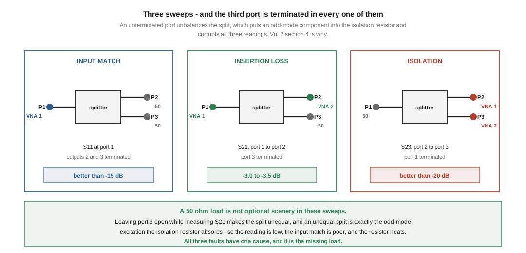
And nothing in the procedure says to terminate the unused port. This is the substantive omission, and Vol 2 §4 supplies the reason. A two-port VNA has two cables; a two-way splitter has three ports; so in every one of these three measurements there is a port with nothing connected to it. Leaving it open makes the split unequal, and an unequal split is precisely the odd-mode excitation the isolation resistor exists to absorb. The consequences arrive together:
- the measured insertion loss reads low, because power is going into the resistor
- the measured input match reads poor, because the even-mode termination is wrong
- the resistor heats, on a bench test at milliwatt levels where nothing should be getting warm
All three symptoms have one cause, and a 50 Ω load on the third port removes all three. The corrected procedure:
Table 3 — All three symptoms have one cause, and a 50 Ω load on the third port removes all three. The corrected procedure
| measurement | VNA port 1 | VNA port 2 | terminate | target |
|---|---|---|---|---|
| input match | splitter P1 | — | P2 and P3 | S11 better than −15 dB |
| insertion loss | splitter P1 | splitter P2 | P3 | S21 between −3.0 and −3.5 dB |
| isolation | splitter P2 | splitter P3 | P1 | S23 better than −20 dB |
The third row is the one most often skipped and the one that actually tests whether the device is a Wilkinson rather than a bare junction — Vol 1 computed a bare junction’s isolation at 3.52 dB, so a splitter reading anything near 20 dB has a working resistor, and one reading 4 dB does not.
Two further notes. Calibrate at the reference plane you care about, meaning with the same adapters in place that will be in place for the measurement; the NanoVNA dive covers the open/short/load sequence. And the loads used for termination are part of the measurement: a mediocre 50 Ω load has a return loss of perhaps 25 dB, which sets a floor on the isolation figure that can be believed, for the same reason Vol 4 §3 gives about directivity.
5.6 The commercial survey, verified 2026-09-17
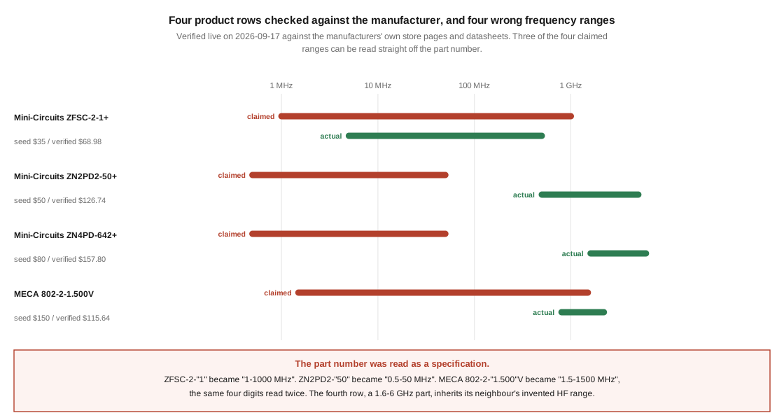
Four of the seed’s product rows could be checked against a manufacturer’s own store page or datasheet. All four were wrong in the frequency column, and all four were wrong in price.
Table 4 — 6. The commercial survey, verified 2026-09-17
| part | seed’s claim | verified | seed’s price | verified price |
|---|---|---|---|---|
| Mini-Circuits ZFSC-2-1+ | 1–1000 MHz | 5–500 MHz, BNC, 1 W | $35 | $68.98 |
| Mini-Circuits ZN2PD2-50+ | 0.5–50 MHz, “HF specialty” | 500–5000 MHz, 0.9 dB loss, 19 dB isolation | $50 | $126.74 |
| Mini-Circuits ZN4PD-642+ | 0.5–50 MHz, “HF 4-way” | 1600–6000 MHz | $80 | $157.80 |
| MECA 802-2-1.500V | 1.5–1500 MHz, 5 W | 0.8–2.2 GHz, 20 W | $150 | $115.64 |
The pattern in the frequency column is the finding. In three of the four, the claimed range is the part number read as a specification:
- ZFSC-2-1+ became “1–1000 MHz”
- ZN2PD2-50+ became “0.5–50 MHz”
- MECA 802-2-1.500V became “1.5–1500 MHz” — the same four digits read twice, once as gigahertz-scaled and once as megahertz
The fourth, the ZN4PD-642+, is a 1.6–6 GHz part that appears to have inherited the invented HF range of the row above it, since the two are presented together as the chapter’s HF two-way and four-way recommendations. The consequence is that the seed’s entire HF transformer-splitter recommendation consists of microwave parts — a reader following it would buy a 500–5000 MHz device to distribute 80 m.
This is a different failure from the ones the earlier volumes found. Those were errors of mechanism, where a real number lost a variable. This is invention: a specification generated from the shape of a string rather than looked up. It sits alongside the fabricated rows this program has found in three previous dives, and it is the failure the program most wants to avoid repeating.
The price column has no single pattern. Three of four are understated, by between 49 % and 97 %; the MECA part is overstated by 30 %. Two of the four verified prices are quantity-one figures from the manufacturer’s own store and will vary with quantity.
5.6.1 What could not be verified, and is therefore not restated
The following rows appear in the seed’s tables and could not be confirmed against any live manufacturer page in this pass. They are listed as unverified rather than repeated as fact or deleted as fictitious, because Vol 3 §9’s caution applies: declaring a real product fictitious is its own failure mode, and this program has done it twice.
- Mini-Circuits ZFBT-282-1.5+ (bias-T) and ZX10-2-12+ (listed as a quadrature hybrid) — the manufacturer’s store returned no content for either designation this pass. The ZX10-2-12+ carries the additional question Vol 3 §9 raised: Mini-Circuits’ quadrature parts are conventionally designated with a Q, and this designation has none. Unverified; the naming question is recorded and not asserted.
- Pasternack PE-Q12-2400, PE7600, PE-W7150, PE-W18-N — not confirmed. Two of these rows carry a further internal marker: they specify couplers in dBi, which is a unit of antenna gain and has no meaning for a directional coupler. Whatever the products’ status, those figures cannot be right as printed.
- Stridsberg BT-300 and MCA20 series, DX Engineering DXE-DP-4-1, ENI 4061-2, Anaren custom couplers, MECA broadband 1 kW — not confirmed.
A note on the search: this session’s web-search budget was exhausted partway through the survey, and the unverified rows above were not all given the same depth of checking as the four in the table. That is a limitation of this pass, not evidence about the products, and re-checking them is recorded as owed work in §8.
One standing caution for anyone reading this hub’s other commercial sections: MFJ Enterprises ceased manufacturing on 17 May 2024, taking its associated brands with it. No MFJ part appears in this chapter’s tables, but several of this hub’s other dives list MFJ products as current, and the antenna-tuners dive has already had to correct eleven of them.
5.6.2 What is worth buying
Stripped of the unverifiable rows, the honest recommendation is short.
For bench and receive work at VHF and above, a Mini-Circuits coaxial splitter of the appropriate band is the reference part, and the lesson of the table is to read the datasheet band rather than the model number. The ZFSC-2-1+ at 5–500 MHz genuinely is a good general-purpose two-way for HF through VHF, which is close to what the chapter wanted it for — it simply is not the 1–1000 MHz part the chapter claimed.
For HF distribution to several receivers, the transformer four-way of §4 is straightforward to build and there is no strong reason to buy. This is the one place in this dive where the DIY option is unambiguously the better answer.
For measurement, a directional coupler’s specification to demand is directivity, per Vol 4 §3, and any vendor who does not publish it is selling on the easy number.
5.7 What to avoid, and what the chapter gets right
The seed’s “what to avoid” list is sound and is confirmed rather than re-derived:
- Splitters with no published S-parameters. Vol 4 §7 sharpened this: the specification whose absence matters most is isolation for a splitter and directivity for a coupler, because both are the hard ones.
- “Multi-band miracle splitters” claiming 0 dB insertion loss. Vol 1 §2 disposes of these structurally — a matched, isolated three-way division cannot beat 4.77 dB, and no construction improves on that.
- Resistive splitters marketed as Wilkinson. A real distinction, and §5’s isolation sweep is the test: a resistive divider reads 6.02 dB of isolation, a working Wilkinson reads 20 dB or better, and the measurement takes a minute.
- Used splitters with a carbonised bridging resistor. Confirmed, and Vol 1 §6 explains what causes it: the resistor dissipates nothing in normal service and everything when the inputs disagree, so a burnt one is direct evidence the device was used as a combiner with a failed or mismatched source.
5.8 Where the dive stands
Five volumes from a 5,415-word chapter. The three-port theorem sets the frame and the Wilkinson escapes it with a resistor that carries no current; four-port hybrids escape it differently and buy phase; the directional coupler divides unequally in order to measure, and its directivity is the error bar on everything it reports; and the build and buy sections here turn all of that into a board, a core and a catalogue.
Owed, and recorded rather than quietly skipped:
- No measurement in this dive is first-hand. Every figure is computed from an idealised network. §5 is written as the bench procedure that would close this in an afternoon with a NanoVNA and three 50 Ω loads, and the first thing worth measuring is whether a real FR-4 Wilkinson’s excess loss matches the conductor-loss prediction of Vol 2 §4.
- No volume has had an independent accuracy review. Author and checker have been the same throughout, which every previous dive in this program has found to be the weakest link.
- The unverified product rows of §6.1 need a second pass with a fresh search budget, particularly the two Mini-Circuits designations that returned empty pages and the ZX10-2-12+ naming question from Vol 3 §9.
- Photographs of a real build. The three photographs in this dive are of other people’s hardware; a built and measured 500 MHz Wilkinson would be the first first-hand content it has.
5.9 Resources
- E. Hammerstad and Ø. Jensen, Accurate Models for Microstrip Computer-Aided Design, IEEE MTT-S, 1980 — the synthesis behind every dimension in §2 and §3.
- D. M. Pozar, Microwave Engineering, 4th ed., ch. 7 — the reference for all five volumes.
- Mini-Circuits ZFSC-2-1+, ZN2PD2-50-S+ and ZN4PD-642W-S+ store pages and datasheets — checked 2026-09-17; the source of §6’s verified frequency ranges and prices.
- MECA Electronics 802-2-1.500V product page (e-meca.com) — checked 2026-09-17.
- BALUNs and UNUNs, Vol 3 — ferrite cores, mix selection and the duty-cycle derating §4’s resistors and transformers need.
- NanoVNA, Vol 3 — the calibration sequence §5 depends on.
- Passive splitters, Vol 2 — the microstrip synthesis and the corporate-tree architecture §3 and §4 build from.
- Antenna tuners, Vol 5 — the other commercial survey in this hub that had to be substantially rebuilt, and the source of the MFJ cessation date.
Comments (0)