Receive-Only Loops & Specialty Receive Antennas · Volume 5
DIY Build, Measurement and Buys
A verification list that names an instrument and then asks it for a number it cannot measure, the one test that would actually settle the question and needs nothing but a step attenuator, a market with two dead manufacturers in it — and a closing myth that is a worked example of the first defect in the dive
5.1 About this volume
Four volumes of argument arrive here. Vol 1 replaced the chapter’s figure of merit. Vol 2 put the beverage’s polarisation the right way up. Vol 3 found the small terminated loops pointing the wrong way and built a ninth too small. Vol 4 found the active loops ranked on a parameter with almost no leverage. This volume builds one, measures it, and buys one.
The chapter’s build section is short, sensible and cheap — a metre of wire, a small amplifier board, a bias tee — and there is nothing wrong with the architecture. What is wrong is the part that tells you whether it worked.
§15.4 lists four success criteria and names a NanoVNA to check them with. Two of the four cannot be measured with a vector network analyser, and one of those two is the headline number the whole chapter ranks products by. §3.
And the one test that matters is absent. Vol 4 established that dynamic range, not sensitivity, separates these units. There is no overload test anywhere in the build. §4 supplies one that needs a step attenuator and nothing else, and which answers Vol 4’s question about the loss budget at the same time.
The buying section repeats §8.2’s trouble and adds to it. §5: a discontinued preamplifier sold as premium, a phasing system that could not be found, and four entries that are not receiving antennas.
⭐⭐ But the chapter also contains the answer to Vol 4’s central complaint, in its accessories list. §6.
⭐⭐⭐ And its final myth is a worked example of the dive’s first defect. §7. That is where this volume ends, because it is the neatest possible demonstration that the argument in Vol 1 was not imported from outside — it was sitting in the chapter’s own closing paragraph.
5.2 Building the loop
The chapter’s §15 specifies a one-metre loop of #14 wire feeding an LZ1AQ-pattern amplifier, powered up the coax through a bias tee, on a fibreglass mast. That is the right architecture and it is worth building. Three things need adjusting.
Use the fattest conductor you can, not #14 wire. Vol 4 quoted the measurement work on this directly: “the loop has to be made from a large diameter conductor or flat strip in order to minimise the overall loop inductance.” A single-turn loop’s inductance is what the amplifier has to work against across a decade of frequency, and thin wire maximises it. Aluminium tube, copper strip, or even coaxial braid flattened out will all beat #14 wire. ⭐ The transmitting loops dive reaches “use the fattest conductor you can” from the loss side; here it is the matching. Both dives end at the same instruction for different reasons.
Credit the design correctly. Vol 4 established that the LZ1AQ amplifier is Chavdar Levkov’s, and that the chapter’s “Joel Wallman” is a misattribution appearing twice — once in §8.4 and again in the §19 resource list. His commercial version is the AAA-1C.
And add up the bill of materials. The itemised parts come to $78; §15’s opening paragraph says “Total parts cost ~$60 USD”. ⭐ This is the third dive running in which a build section’s headline total disagrees with its own table — the transmitting loops dive had $250 against $322. Adding up the column is a thirty-second check that keeps catching things.
⚠ The enclosure line specifies a Hammond 1591 again, which for a five-centimetre amplifier board is entirely appropriate — unlike the transmitting-loops case, where the same family was specified for a part that could not fit in it. Confirmed, not corrected.
5.3 The verification that cannot verify
§15.3 ends the build with an instruction:
Test with NanoVNA. Power the LNA via the bias-T. Sweep the LNA’s output. Should see flat gain across 10 kHz – 30 MHz.
and §15.4 lists what success looks like:
Table 1 — and §15.4 lists what success looks like
| criterion | measurable with a VNA? | |
|---|---|---|
| Gain at 1 MHz: +10 to +15 dB | yes | a VNA measures gain |
| Frequency range 10 kHz – 30 MHz, flat | yes | this is exactly what the sweep shows |
| Noise figure: 2–3 dB | 🔴 no | a vector network analyser cannot measure noise figure |
| SNR 5–10 dB better than a random wire | 🔴 no | an on-air comparison, not a bench test |
🔴 Half the acceptance criteria cannot be checked with the instrument the same section names. Noise figure needs a calibrated noise source and a noise-figure meter, or a Y-factor measurement with a known excess-noise-ratio head — none of which appear anywhere in the chapter. The SNR comparison needs two antennas, a switch, and a signal that stays put long enough to compare, which is a field exercise rather than a build check.
🔴🔴 And the test that would actually matter is missing entirely. Vol 4 showed that these amplifiers are separated by dynamic range: an LNA at the antenna has no preselection in front of it, and the reported failure mode of the chapter’s own budget recommendation is intermodulation, not insensitivity. There is no overload test in §15.
⭐ This is the same shape as a defect the antenna tuners dive found: a verification step that exercises the one case needing no verification. There it was “test with a 50 Ω dummy load” — the single condition under which a tuner does nothing. Here it is a gain sweep, which will look identical on an amplifier that is about to be flattened by the local broadcast station and on one that is not.
⚠ The gain sweep is still worth doing. It catches oscillation, a dead stage, a wrong bias point and a badly mismatched loop, and the chapter is right that a flat response across the range is what a working build looks like. It is a necessary test presented as a sufficient one.
5.4 The test that works
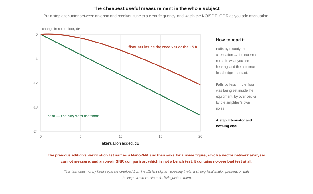
There is a measurement that answers both open questions — is the antenna delivering external noise above the amplifier, and is anything overloading — and it needs a step attenuator and nothing else.
Connect the antenna, tune to a clear frequency, and note the noise floor. Then add attenuation and watch what the floor does.
Table 2 — Connect the antenna, tune to a clear frequency, and note the noise floor. Then add attenuation and watch what the floor does.
| attenuation added | a linear system | an overloaded or amplifier-limited one |
|---|---|---|
| 6 dB | −6 dB | less than 6 dB |
| 10 dB | −10 dB | less than 10 dB |
| 20 dB | −20 dB | less than 20 dB |
⭐⭐ If the noise floor falls by exactly the attenuation you added, the external noise is what you are hearing, the antenna is delivering it well above the amplifier, and Vol 4’s loss budget is intact. The attenuator is removing signal and noise together, and the ratio between them — the only thing that matters — is unchanged, which is Vol 1’s “loss is free” demonstrated on a bench.
⭐⭐ If the floor falls by less than the attenuation, something inside the equipment is setting it. Either the amplifier’s own noise has become the floor — meaning the loss budget has run out — or the system is being driven into distortion by something out of band, and the “noise” you are hearing is manufactured rather than received.
⚠ The test does not, on its own, separate those two causes. Two follow-ups do. Repeat it while a strong local station is present: if the shortfall worsens, it is overload. Or rotate the loop into its null: if the floor barely moves, the floor is not coming from the antenna at all.
⭐⭐⭐ This is the cheapest useful measurement in the whole dive, and it is the one that would let a builder check the claims in Vol 4 at their own site — where, per Vol 4 §2, the answer genuinely differs between a city and a quiet valley.
⭐ It also gives the dive’s one bench-measurable number. Vol 1 said external noise sits 22 to 55 dB above a receiver. The attenuation at which the noise floor stops tracking is a direct measurement of that margin at your location, which is a more useful figure than any published table, because it is yours.
5.5 Buying the passive side
Vol 4 surveyed the active loops. This section covers the rest of §16, checked against live pages on 3 August 2026.

Table 3 — 5. Buying the passive side
| the chapter’s entry | status |
|---|---|
| DX Engineering RPA-1, $800, “premium” | 🔴 the product page reads “DISCONTINUED … Not Available” and directs buyers to the RPA-2 |
| DX Engineering RAPS phasing system, $1,500–3,000 | 🔴 could not be found under that name. DXE’s phasing product is the NCC-2; its array product is the Receive Four Square |
| DX Engineering Beverage kit, $200 | ✅ the Beverage Antenna System Combos exist and bundle the feedpoint transformer with a preamp |
| DX Engineering K9AY kit, $400 | ⚠ unverified at that price; the K9AY system is sold by Array Solutions as the AS-AYL-4 |
| Tecsun H-501, PL-660 | ⚠ receivers, not antennas — they belong beside Vol 4’s ferrite section, not in a table of receiving antennas |
| KrakenSDR + 4 antennas, $700+ | ⚠ a coherent direction finder, not a receiving antenna. A different problem |
⭐⭐⭐ And the most useful thing in this section is a specification line the chapter never quotes. DX Engineering’s own description of the RPA-1:
Preamplifier, Receive, 300kHz-35 MHz, 16dB Gain, 110dB Dyn. Range, Type F+Phono, 12-18 Vdc
Gain, frequency range, and dynamic range. No noise figure. The manufacturer of the premium receive preamplifier in the chapter’s own table leads with exactly the parameter Vol 4 argued should rank these products, and omits the one the chapter ranks them by.
⭐ The commercial market already knows. This dive did not import an outside standard; it noticed that the chapter was not using the one already in use.
⚠ Across both buying sections, sixteen rows contain: two manufacturers that have stopped trading, one discontinued part, one product that could not be found, one fabricated attribution, and four entries that are not receiving antennas. ⭐ A buying guide dates faster than any other part of a reference, which is why this one carries its check date on its face — and why the next reader should re-run it rather than trust it.
5.6 Companion gear, and the answer buried in it
§17’s list is short and mostly right: a bias tee, termination resistors, switching, ground rods, lightning protection.
⚠ One item repeats Vol 3’s inverted advice: “Termination resistor (non-inductive, 5–10 W) … Vishay metal-film”. Metal-film resistors are spiral-trimmed and can be markedly inductive; carbon composition is the non-inductive family. And 5–10 W is even further over-specified than §2.3’s 2–5 W, for a component dissipating picowatts. See Vol 3 §8 — including the reason the chapter’s instinct to fit something substantial is not wrong, just wrongly justified.
⭐⭐⭐ But the last item on the list is the chapter answering Vol 4’s complaint against itself:
Receive antenna pre-selector / bandpass filter — DX Engineering NCC-2 nullables, Inrad bandpass filters; rejects out-of-band signals that could overload the LNA
The chapter knows about overload. It knows an LNA at the antenna can be driven out of its linear range by signals it is not even trying to receive, and it knows the fix. That knowledge lives in an accessories list, three sections after a product table that ranks eight amplifiers without mentioning it once.
⭐⭐ This dive has now found that shape four times — in the transmitting loops dive, where §3.3 gave the correct capacitor voltage that §11 then contradicted; in this chapter’s §4.2, which states RDF in plain language without naming it; in Vol 2’s length table, which pointed the right way while the prose overruled it; and here. The recurring failure is not ignorance. It is that the right fact is present and not connected to the recommendation that needed it.
5.7 The myths, and the one that proves the point
§18’s myth list is the strongest part of the chapter. Most of it is correct and useful, and several entries deserve saying again:
- ✅ “K9AY is omnidirectional — no, it’s cardioid”. Correct, and it is the whole point.
- ✅ “Active loops work fine inside a building — partially true”, with the right reason: building wiring and ductwork couple local noise into the loop.
- ✅ “My active loop got blown by transmitting nearby”. Correct, and worth the warning.
- ✅ “The receive antenna’s SWR doesn’t matter — true within reason”. Correct, and it is Vol 1’s loss-is-free argument arriving from another direction.
- ✅ “Beverage needs a perfect ground at the termination” — the chapter cites a measurement showing a sixteen-radial ground buys less than half a decibel over one rod. ⚠ Cited to ON4UN but not verified here.
⚠ One is inverted, and Vol 4 already fixed it: “A ferrite rod has a figure-8 pattern with deep nulls perpendicular to the rod’s axis”. The nulls are off the ends, along the axis. ⭐ The operating advice attached to it — rotate the radio to null an unwanted station — is right, which is the usual shape here: the practice is correct and the stated direction is not.
5.7.1 And then the last one
“Phased array F/B is the sum of two individual F/Bs” — sometimes. Two beverages combined in proper phase produce 30–35 dB F/B (vs 22 dB each). Phased arrays multiply directional benefit when properly aligned and aimed.
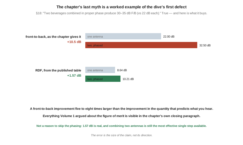
Everything in that paragraph is true. Now put the published RDF beside it, for exactly that pair of antennas:
Table 4 — Everything in that paragraph is true. Now put the published RDF beside it, for exactly that pair of antennas
| one antenna | two, phased | improvement | |
|---|---|---|---|
| front-to-back, as the chapter gives it | 22 dB | 30–35 dB | +8 to +13 dB |
| RDF, from the published table | 8.64 dB | 10.21 dB | +1.57 dB |
⭐⭐⭐ The chapter’s closing myth is a worked example of this dive’s opening defect. It quotes a front-to-back improvement five to eight times larger than the improvement in the quantity that predicts what the operator will actually hear — and it does so in a paragraph whose purpose is to correct a misconception.
That is where the argument in Vol 1 came from. Not from an outside standard imposed on the chapter, but from the chapter’s own numbers failing to mean what it takes them to mean.
⚠⚠ And it is not a reason to skip the phasing. 1.57 dB is a real improvement, and Vol 1 §7 found that combining two antennas moves the number more than perfecting any single one. The chapter’s advice is right; only the size of the claim is wrong.
5.8 Where this volume, and this dive, hand off
The build is sound and cheap, and the correction to it is one line: use a fat conductor, because the amplifier has to work against the loop’s inductance across a decade. What needed replacing was the verification — a list that names a vector network analyser and then asks it for a noise figure, omits the only test that would separate a good amplifier from a bad one, and would look identical on a build about to be flattened by the local broadcast station. §4’s attenuator test costs one component and answers both questions the dive has been carrying.
And the chapter’s last paragraph closes the circle. A pair of phased beverages improves front-to-back ratio by eight to thirteen decibels and RDF by one and a half, and the chapter reports the first figure while describing the second’s benefit. That is the dive’s whole argument, written by the chapter itself.
The dive is complete at five volumes.
- Vol 1 — the noise regime from ITU-R P.372, and RDF against front-to-back ratio.
- Vol 2 — the beverage, wave tilt, and the only antenna in this hub that wants bad soil.
- Vol 3 — the small terminated loops, and the sentence from their designer that settles their geometry.
- Vol 4 — active loops, the loss budget, and dynamic range as the real discriminator.
- Transmitting loops, Vol 4 — the companion dive that handed this one the noise material.
- Fixed vertical monopoles, Vol 1 — the omnidirectional baseline, and the ground system a beverage does not want.
- Baluns and ununs, Vol 4 — every transformer in this dive.
Five things are owed, and they are worth listing plainly.
No measurement in this dive is first-hand. Every figure is computed or published. §4 is written as the procedure that would change that in an afternoon.
A dipole’s RDF over real ground, which is the comparison the chapter makes throughout and which Vol 1 could not close.
A NEC model over defined soil, which would settle Vol 2’s twenty-decibel gain discrepancy and replace its ground-free pattern model.
A null-depth sweep against termination value, which Vol 3 needs for both the depth and the angle of the null.
And a two-tone intermodulation test, published for one of eight products, which is the measurement that would rank the active loops properly.
⏳ No volume in this dive has had an independent accuracy review. Author and checker have been the same throughout, and every previous dive in this program has found real defects in every volume when a fresh reviewer looked.
5.9 Resources
- Martin, G8JNJ, measurements of the MLA-30 loop amplifier — the conductor-size point in §2, carried from Vol 4.
- DX Engineering product pages — the RPA-1’s discontinued status and published specification line in §5, and the Beverage Antenna System Combos.
- Array Solutions AS-AYL-4 — the K9AY system referenced in §5.
- LZ1AQ (Chavdar Levkov), active antenna amplifier documentation — the correct attribution for the amplifier in §2.
- ON4UN, Low-Band DXing — the termination-ground measurement cited in §7, and the standard reference throughout this dive.
- W8JI, receiving-antenna RDF comparison — the phased-beverage figures in §7.
- Vol 1 — RDF, the noise regime, and the argument §7 closes.
- Vol 2 · Vol 3 · Vol 4.
- Transmitting loops, Vol 1 — the same conductor-size conclusion from the loss side.
- Transmitting loops, Vol 2 — the right-answer-in-the-wrong-section shape §6 recognises.
- Antenna tuners, Vol 5 — the verification-that-verifies-nothing defect §3 matches.
Comments (0)