Single-Band Dipoles · Volume 5
DIY Build, Tuning & Measurement + Commercial Buys & Deployment
Power-handling limits and failure modes; a complete 40 m half-wave build with real part numbers; the NanoVNA cut-long-hoist-sweep-trim workflow; a ranked, dated commercial-buy survey; companion gear; and the gotchas that catch first-time builders
5.1 About this volume
The first four volumes of this dive built the half-wave dipole from first principles and left it as a clean electrical abstraction: a standing-wave current distribution (Vol 1), a 73 + j42.5 Ω feedpoint that a 1:1 current balun tames (Vol 2), a radiation pattern and SWR curve that vary with height and frequency (Vol 3), and a family of mechanical variants that trade the clean reference geometry for deployability (Vol 4). This volume is where all of that lands on a workbench, a spool of wire, and a rope. It closes the dive by answering the two questions every one of those volumes has been forward-referencing: how do you actually build one, and if you’d rather not, what do you buy instead.
Those two questions get equal weight and full structural treatment, not an appendix each. Section 3 and Section 4 are a complete, real-parts bill of materials and construction sequence for a 40 m half-wave dipole — the canonical “first serious wire antenna” build, chosen because it is legal-limit capable, mechanically manageable on a typical residential or rural lot, and squarely in the “full 468/f table” territory of Vol 1 §6. Section 5 turns the cut-long wire into an on-frequency antenna with a NanoVNA, formalizing the “cut, hoist, sweep, trim” loop that every earlier volume has cited but none has walked through. Section 6 is the commercial-buy survey — real, current, dated products at three price tiers, because a builder who would rather spend money than an evening should get an equally rigorous answer. Sections 7 and 8 round out the practical picture (companion gear, and the myths that cost people a season of degraded operation), and Section 9 closes the whole five-volume dive.
One housekeeping note before the parts list: every price, part number, and product in this volume was checked against a live vendor page or product datasheet as of early July 2026, and is marked accordingly. Antenna-parts pricing and SKUs move — the Antennas project’s own known-constraints note flags exactly this — so treat the numbers here as accurate at time of writing and re-verify before a big order. Where a specific number could not be pinned down from a public listing, that is stated explicitly rather than invented; a hedged approximate figure beats a fabricated precise one.
5.2 Power handling — limits and failure modes
A wire dipole’s power ceiling is not set by one number; it is set by whichever of three independent limits is lowest for your specific build, and knowing which one binds is the difference between a dipole that runs 1.5 kW for twenty years and one that arcs or overheats the first contest weekend.
The wire itself is almost never the limit. #14 AWG stranded copper — the standard HF dipole gauge — carries legal-limit amateur power (1.5 kW PEP SSB, effectively 1 kW average CW/digital key-down) with no meaningful heating; the conductor’s current-carrying capacity at HF is tens of kW before ohmic heating becomes a concern, and the mechanical limit (wind and ice loading on the wire and its terminations, on the order of a few tens of kilograms of break strength for #14 copperweld or copper-clad steel) binds long before the electrical one does. Thinner wire changes this materially: #18 magnet wire or fine stealth wire is realistically a 100–200 W antenna before the strand starts to anneal and fatigue at the terminations under RF current and wind flex, which is why stealth-wire builds (Vol 4 and the hub’s stealth-deployment volume) are QRP-to-100W propositions rather than legal-limit ones. Going the other direction, #12 or #10 wire raises the thermal ceiling further, at the cost of a slightly heavier, stiffer element and a marginally lower trim factor k (Vol 1 §4). For amateur HF, #14 is the sweet spot: legal-limit capable, cheap, and easy to strip, solder, and terminate.
The end insulators are a high-voltage component, not string-tie hardware, and Vol 1 §2 already established why: the element’s ends sit at the standing-wave voltage maximum. At 1.5 kW into a resonant ≈70 Ω feedpoint, the peak RF voltage at the tips of a thin half-wave dipole runs to several kilovolts — the classic figure quoted in the literature is on the order of 4–5 kV peak for a 1.5 kW legal-limit dipole, scaling with the square root of power (V ∝ √P) and rising further on an antenna that is mismatched or fed with high SWR. A quality ceramic egg or dogbone insulator is rated in the tens of kilovolts — comfortably above this — and the failure mode that actually shows up in the field is not dielectric puncture of the ceramic itself but surface tracking and arcing across a wet, dirty, or UV-degraded plastic insulator, or corona loss at a sharp burr left on a cut wire end near the high-field tip. A cheap injection-molded polymer insulator with a thin cross-section, left to collect grime and moisture, is the part that arcs — not because its bulk dielectric strength is inadequate, but because a wet, contaminated surface path shortens the effective creepage distance. The fix is boringly simple: buy an insulator with a long creepage path (ribbed ceramic dogbones and eggs are shaped exactly for this), keep the surface clean, and dress any cut wire ends smooth rather than leaving a sharp snipped point sitting at the voltage maximum.
The balun is, in practice, the actual power-handling bottleneck for most home-built dipoles, and this is the failure mode builders most often get wrong because it hides behind a “1.5 kW rated” sticker that describes the RF connector and the wire, not the core. A wound ferrite choke’s power rating is set by core heating, exactly as Vol 2 §8 developed: the differential-mode current is nowhere near the wire’s thermal limit, but common-mode energy and the differential flux swing dissipate as core loss in the ferrite, and if the common-mode impedance is inadequate, or an SWR mismatch drives extra circulating current through the choke, that core heats, its permeability and loss both worsen with temperature, and a sustained key-down can run the core into thermal runaway — the classic symptom being a balun enclosure that gets uncomfortably warm on a long CW contest exchange or an FT8 duty-cycle transmission, followed eventually by a cracked or de-tuned core. A commercial balun’s published power rating (Section 3 gives real numbers: 3 kW continuous for the Balun Designs Model 1115, 5 kW for the DX Engineering Maxi-Core) is a heating-limited SSB/CW figure measured into a reasonably matched load, not a hard wire-current ceiling — feed the same balun a badly mismatched, high-SWR load and its effective power handling drops, because more of the applied power turns into common-mode current the core has to dissipate rather than differential-mode power the antenna radiates. The practical guidance is threefold: match the balun’s rating to the mode (continuous digital modes and CW key-down are far harder on a core than SSB’s low average duty cycle, so budget to the CW/digital number, not the SSB number, if you run those modes at high power); oversize rather than undersize for a legal-limit amplifier station (the FT290-size 2.9″ toroid over the FT240-size 2.4″ one, or a commercial balun explicitly rated above your amplifier’s output); and fix a bad match rather than trusting the balun to absorb it — a balun is not a substitute for a resonant, well-trimmed antenna, and running one hot because the antenna is off-frequency is exactly the failure mode that shortens its service life.
The synthesis worth carrying forward into the BOM: for a legal-limit (1.5 kW PEP) 40 m dipole built from #14 wire with quality ceramic insulators and a properly sized 1:1 current choke, none of the three limits bind under normal SSB/CW operation, and the antenna is good for decades of service. The place to spend care is the balun sizing and the insulator surface condition — the wire and the ceramic bulk dielectric were never going to be the weak link.
5.3 DIY build — the bill of materials
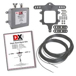
This is the canonical “first serious wire antenna” build: a resonant 40 m half-wave dipole, center-fed, on a 1:1 current balun. Budget roughly 60–90 minutes of bench assembly, an afternoon for the hoist-sweep-trim loop of Section 5, and — at the prices below, checked against live vendor listings in early July 2026 — somewhere around $150–260 depending on whether you buy or wind the balun and whether you use insulated premium wire or bare copperweld.
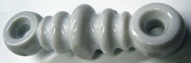
Table 1 — 3. DIY build — the bill of materials
| Part | Specification | Source (verified) | Price (early July 2026) |
|---|---|---|---|
| Antenna wire | 14 AWG, 19×27 stranded copper, UV-resistant black PVC jacket, 150 ft spool (more than enough for both legs plus termination slack) | DX Engineering DXE-ANTW-150 — verified live listing | $49.99 |
| Antenna wire (bare alternative) | 14 AWG CopperWeld (copper-clad steel), 100 ft | The Wireman / Amateur Radio Supplies CW14-100 — verified live listing | $21.99 |
| Center-T + end insulator kit | EZ-BUILD® no-solder serpentine-grip center-T insulator + 2 matching end insulators + stainless hardware + crimp terminals; accommodates up to 4-gauge wire | DX Engineering DXE-UWA-KIT — verified live listing | $30.49 |
| Center insulator (alternative) | Molded center connector with built-in SO-239, strain-relief eye | Budwig HQ-1 — verified at Universal Radio | $14.95 (add ceramic dogbone/egg end insulators separately, ~$5–8 each) |
| 1:1 current balun | 1–31 MHz (usable to 54 MHz), 3 kW continuous, custom Fair-Rite ferrite mix on a 2.4″ core, SO-239 | Balun Designs Model 1115 — verified on manufacturer site | $84.95 |
| 1:1 current balun (DIY alternative) | FT240-31 toroid core (Fair-Rite mix 31), 12 turns #14 PTFE hookup or enamel wire, SO-239 bulkhead + weatherproof enclosure | Core: Fair-Rite 2631803802 (DigiKey) — verified live listing | Core $9.36 + enclosure/connector ≈ $20–30 |
| 1:1 current balun (factory kit alternative) | 5 kW-rated Maxi-Core® 1:1 choke, included pre-wired in the DX Engineering resonator-dipole kit (Section 6) | DX Engineering DXE-MC20-1-1 — bundled in DXE-RDPK series | (bundled — see Section 6 if buying the whole kit) |
| Halyard rope | 3/16″ double-braided Dacron/polyester, 770 lb break strength, UV-stabilized, 500 ft (a lifetime supply for one antenna) | DX Engineering / Synthetic Textile Industries SYN-DBR-187-500 — verified live listing | $85.99 (a 50–100 ft cut is all one dipole needs; buy the full spool if you’ll build more) |
| Coax pigtail | RG-8X, PL-259 to match the balun’s SO-239, ~1–3 m | Generic — any quality RG-8X with crimp or solder PL-259s; no single SKU is canonical here | ≈ $12–20 |
| NanoVNA | 10 kHz–1.5 GHz+, 4″ touchscreen, includes SMA OSL calibration kit, USB-C | Nooelec NanoVNA-H4 — verified on manufacturer site | $124.95 (one-time tool cost, not consumed per build) |
| Weatherproofing | Self-amalgamating rubber tape + vinyl overwrap | 3M Scotch 130C (rubber splicing tape) + 3M Super 33+ (vinyl electrical tape) — both standard, widely stocked | ≈ $15 combined |
Reading the table. The wire and rope spools are sized so one purchase covers the whole build with plenty left over for a second antenna or for the inevitable re-terminate-after-a-storm repair — buying the 150 ft wire spool and a shorter cut of rope, rather than the full 500 ft spool, is the more sensible one-antenna purchase; the per-foot economics favor the bulk spool only if more builds are planned. The balun is where the real cost fork sits: $84.95 for a factory Balun Designs 1115 versus roughly $30–40 in parts for a DIY FT240-31 winding (core plus enclosure plus connector), the difference being an evening of toroid winding and the assurance of a lab-measured choking-impedance curve on the commercial part. Both are legitimate choices; Vol 2 §7–8 has the winding theory (turns count, mix selection, choking-impedance target) if you go the DIY route. Total for a fully commercial-balun build: roughly $185–210 with the premium PVC-insulated wire, or $155–180 with bare copperweld — these figures exclude the halyard rope (assume a short cut on hand, or budget ~$15–25 for a 100–150 ft length rather than the $85.99 bulk spool) and exclude the NanoVNA (a reusable tool, not a per-build consumable); with those added, the build still sits comfortably inside the “$150–260” estimate above.
5.4 DIY build — construction, step by step
The dimensioned worked example below is a 40 m dipole resonant at 7.150 MHz, chosen to land in the middle of the phone sub-band; recompute every length linearly from Vol 1 §6’s table for a different design frequency or band.
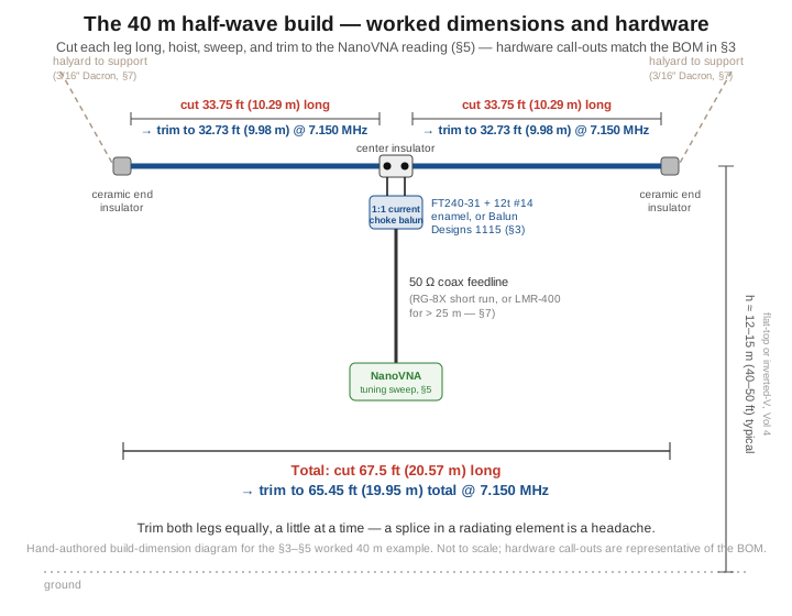
Cut the wire long. Vol 1 §6 gives 65.45 ft (19.95 m) total, 32.73 ft (9.98 m) per leg, as the trimmed resonant target for 7.150 MHz on thin #14 wire. Cut two lengths at roughly 3% over that — about 33.75 ft (10.29 m) each, a little over a foot of headroom per leg — rather than cutting to the exact calculated length. The reasoning is entirely one-directional: a pair of side cutters only ever makes a wire shorter, so any error in the trim factor, an insulator that adds more end capacitance than assumed, or a support height that detunes the element low, is recoverable by trimming further; a wire cut exactly to length that turns out slightly short is not recoverable without a splice, and a spliced radiating element is a mechanical and RF headache best avoided entirely. The generous headroom here is deliberately larger than the fine trim increments in Vol 3 §9’s per-band sensitivity table — that table is for the last few kilohertz of correction near resonance; the initial cut is a coarser first pass that the sweep-and-trim loop of Section 5 walks down onto frequency over a few iterations.
Terminate the ends. If using the DXE-UWA-KIT’s no-solder serpentine grip, thread each wire end through the end insulator per its instructions — the grip geometry holds the wire under tension without a solder joint or a doubled-back splice, which is the whole point of that product line. If using traditional ceramic egg or dogbone insulators, loop the wire end through the insulator’s eye, double back 12–15 cm, wrap 6–8 turns tightly around the standing wire, and solder the wrap. The doubled-back wrap carries the mechanical strain; the solder is corrosion insurance at the electrical joint, not the mechanical fastener. A properly wrapped-and-soldered end outlasts the wire’s UV jacket; a bare twist without solder works loose over one or two seasons of wind flex.
Terminate the center. Each wire’s inboard end lands on the center insulator’s terminal — again, the DXE-UWA-KIT’s serpentine grip needs no solder, while the Budwig HQ-1 or an equivalent molded center insulator takes a soldered ring-terminal lug on each of its two stud terminals. The two legs must be electrically isolated from each other at this point — they meet only through the balun’s transformation, never by a direct jumper — and the terminal spacing (typically 5–8 cm) is the physical realization of the feed gap in Vol 1 §2’s standing-wave picture.
Install the balun. A factory unit like the Balun Designs 1115 bolts directly to the center insulator’s studs (or its own bracket, per the WA-BMB-style mounting hardware bundled with the DX Engineering kits) and takes the coax pigtail on its SO-239. A DIY FT240-31 winding — 12 turns of #14 enameled or PTFE wire through the core, per Vol 2 §7’s winding guidance — needs its two winding ends bonded to the center-insulator terminals and its other two ends (or, in a coax-wound choke, the coax itself) run to the feedline connector, all potted in a weatherproof enclosure (a small ABS or fiberglass project box with cable glands works; the Hammond 1590/1591-series enclosures are a common, generic choice with no single canonical SKU for this application).
Add halyards. Cut two lengths of the 3/16″ Dacron rope, each long enough to reach from the end insulator over its support point (a tree branch, a mast arm) and back down to a ground-level tie-off with a few meters of service slack. Tie a stopper knot (a figure-8-with-follow-through, or a bowline if you prefer a loop) at the insulator end so the rope cannot slip back through under load.
Hoist and take a first sweep. Raise the dipole to its intended operating height — 12–15 m (40–50 ft) is a good general-purpose figure for 40 m per the height-versus-takeoff-angle development in Vol 3 §6 — and connect the calibrated NanoVNA at the feedline’s shack end (Section 5 covers the calibration step; do it before this sweep, not after). Sweep a span comfortably wider than the expected error, e.g. 6.8–7.5 MHz, and read where the SWR or return-loss minimum actually sits.
Trim. Lower the dipole, remove a small, equal amount of wire from each end — Vol 3 §9’s trim-sensitivity table gives the per-band cm-per-kHz figure to convert “resonance is X kHz low” into “trim Y cm off each leg” — re-terminate, re-hoist, and re-sweep. Two to three iterations is typical for a well-executed first cut; more than four or five means something other than simple length is detuning the antenna (a nearby conductor, a bad balun, or a miscounted length) and is worth diagnosing before trimming further.
Lock and weatherproof. Once the sweep lands within about 10 kHz of the target, apply 3M Scotch 130C self-amalgamating rubber tape to the balun-to-coax connector junction, then overwrap with 3M Super 33+ vinyl tape for UV protection — rubber tape alone degrades in sunlight, and vinyl tape alone does not seal against water ingress, so the two-layer combination is standard practice, not belt-and-suspenders excess. The deeper weatherproofing treatment (coax-seal mastic, connector selection, corrosion prevention) belongs to the hub’s dedicated weatherproofing volume, cited here rather than repeated.
5.5 Tuning with a NanoVNA — cut long, hoist, sweep, trim
Calibrate first, every time. A NanoVNA’s raw measurement includes the electrical length and loss of whatever is between its port and the thing being measured, so the standard OSL (Open-Short-Load) calibration establishes a known reference plane before any antenna measurement means anything. With the calibration menu open on the device: connect the Open standard to CH0/port 1 and select OPEN; remove it, connect the Short standard, and select SHORT; remove that, connect the Load (50 Ω) standard, and select LOAD; then select DONE and save the result to one of the instrument’s calibration slots. A quick sanity check on the Smith chart display confirms it worked — the open point should sit at the extreme right edge of the chart, the short at the extreme left, and the load dead center. Calibrate at the end of whatever cable you’ll actually measure through — at the antenna feedpoint itself for the cleanest number, or at the shack end of a known feedline if climbing to the feedpoint for every sweep is impractical (in which case remember that the feedline’s own loss and length are now baked into the reference plane, and a long or lossy line will read a rounder, less sharp SWR dip than the true feedpoint impedance).
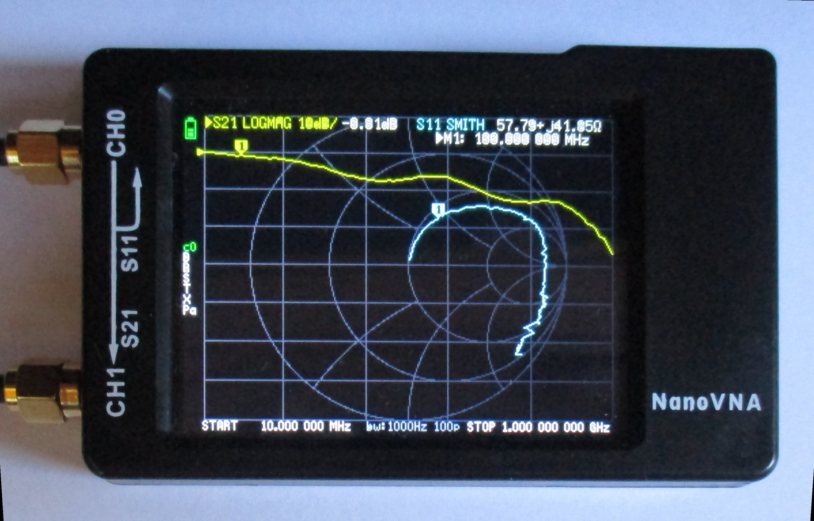
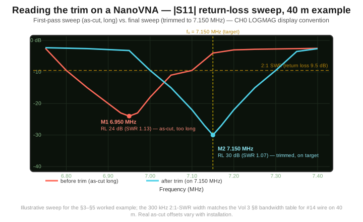
Sweep, and read the minimum, not just the number at your operating frequency. With the calibration saved and the antenna connected, set a sweep span comfortably wider than the expected error (Section 4’s first-pass sweep example: 6.8–7.5 MHz around a 7.150 MHz target) and look at either the SWR trace or the |S11| return-loss trace (LOGMAG in NanoVNA-Saver terminology) — they carry the same information; return loss in dB converts to SWR via SWR = (1+|Γ|)/(1−|Γ|) with |Γ| = 10^(−RL/20), so a 9.5 dB return loss is exactly the 2:1 SWR point, and anything deeper than about 20 dB is an excellent match by any practical standard. The number that matters for tuning is where the trace dips, not what the SWR reads at your intended frequency — a wire cut long resonates below the target, so if the minimum sits at, say, 6.95 MHz when you wanted 7.150 MHz, the antenna is electrically too long and needs trimming; if the minimum sits above the target, the wire somehow came out short (a rare outcome if you followed the cut-long rule, and worth double-checking your arithmetic before assuming the antenna itself is at fault).
Trim symmetrically and re-sweep. Remove wire from both ends equally — an asymmetric trim shifts the effective feed point off the geometric center, subtly degrading the clean figure-8 pattern of Vol 3 §2 even though the SWR dip can still land on frequency. Vol 3 §9’s trim-sensitivity table is the reference for how much to remove: on 40 m, its cited figure is roughly 1.5 cm per side per kHz of upward shift needed, and the general rule across every band is the same 1/f² scaling that table develops — the higher the band, the more delicate the trim, to the point that VHF trimming is done with a file rather than side cutters. Re-terminate the freshly cut ends, re-hoist, and re-sweep; converging within a couple of iterations is normal, and each iteration should move the dip noticeably closer to target if the trim amount was estimated correctly.
What a good final sweep looks like. A properly built and trimmed 40 m dipole should show, at minimum: an SWR minimum below about 1.3:1 (a resonant thin-wire dipole is more typically 1.1–1.2:1 into 50 Ω, per the ~70 Ω resonant feedpoint Vol 2 §2 derived); the minimum landing within roughly 10 kHz of the design frequency; a Smith-chart marker sitting close to the real axis at resonance (reactance near zero); a 2:1-SWR bandwidth in the 250–350 kHz range matching Vol 3 §8’s table for #14 wire on 40 m; and — critically — no shift in the SWR minimum when you flex or re-route the feedline. That last check is the fingerprint of a properly choked feedpoint: if grabbing the coax a meter below the balun and moving it changes the sweep, common-mode current is still riding the shield and the balun is not doing its job (Vol 2 §6), which is a balun problem to fix, not a length problem to trim around.
5.6 Commercial buys — ranked, with price tiers
For the builder who would rather spend money than an evening — or who wants a factory-tuned reference to sanity-check a homebrew build against — the following are current, verified single-band dipole products as of early July 2026. Every product below was checked against a live manufacturer or authorized-dealer listing; where a specific current price could not be confirmed from a public source, that is stated rather than guessed.
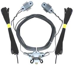
Table 2 — 6. Commercial buys — ranked, with price tiers
| Tier | Product | Band(s) | Price (early July 2026) | Notes |
|---|---|---|---|---|
| Budget | Alpha Delta DX-40 | 40 m | $99.99 (verified, DX Engineering) | Pre-tuned single-band full-size dipole, 67 ft, 12 AWG PVC-insulated solid copper, Delta-C center insulator with built-in static-electricity protection, 2000 W rated, SO-239 feed, minimum recommended feed height 25 ft. The clean, no-assembly-required budget entry; the same DX-series line covers other single bands (DX-20, DX-80, etc.) at similar pricing. |
| Budget (DIY kit) | MFJ-1779B (80/40 m) or MFJ-1779C (20–6 m) | 80/40 m or 20–6 m, user-trimmed | Not published on the current DX Engineering listing at time of writing (custom-order status) — historically a sub-$60 kit; treat as approximate | A cut-to-length kit, not a pre-tuned antenna: 14-gauge 7-strand hard copper wire up to 135 ft, molded center insulator with built-in SO-239, glazed ceramic end insulators, solderless crimp construction, 1500 W rated, band-specific cutting chart included. The bridge product between “build it yourself” and “buy it finished” — you still do the Section 5 tuning loop, but the hardware is pre-selected and matched. |
| Mid | DX Engineering DXE-RDPK-6040 (and the sibling DXE-RDPK-8075, -30-17, -15-6, -160 for other band pairs) | User-cut to resonate on either of two adjacent bands (e.g. 60 or 40 m) | $235.46 (verified, DX Engineering) | The BOM-in-a-box: 46 ft/leg of 14 AWG insulated stranded copper with pre-crimped ring terminals, a DXE-MC20-1-1 Maxi-Core® 1:1 balun rated to 5 kW, a WA-BMB mounting bracket, UV-resistant polyresin end insulators, stainless hardware, and instructions. Effectively Section 3’s BOM pre-assembled with a heavier-duty balun than the DIY build defaults to — the honest “I don’t want to shop for six separate parts” option. |
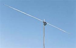
| Premium | Cushcraft D-40 (“World Ranger” rotatable dipole) | 40 m (rotatable — bidirectional, not omnidirectional) | Price not published on current listings at time of writing (multiple retailers show “custom order” / “not available” status) — historically priced in the several-hundred-dollar range for this antenna class; treat as approximate and needing a current quote | Aluminum-tubing rotatable monoband dipole, 1500 W, 21.1 ft turning radius, 50 Ω feed, aimed at the operator who wants a rotatable single-band element on a tower rather than a fixed wire span — a fundamentally different mechanical proposition from everything else in this table, and the entry point into the rotatable-dipole product family that also includes the multi-band Cushcraft D-4 (10/15/20/40 m), which belongs to the multi-band dipole dive rather than here. |
What to avoid. Unbranded “1 kW dipole” listings on general marketplaces that do not specify a balun at all — a direct-soldered coax-to-wire junction with no choke is exactly the common-mode fault Vol 2 §6 describes, and it will put RF in the shack and skew the pattern regardless of how good the wire and insulators are. Any dipole kit advertised as requiring no soldering and no crimping anywhere in its assembly is worth a skeptical second look at the actual termination method in the listing photos — the DXE-UWA-KIT’s serpentine no-solder grip is a legitimately engineered mechanism verified above, but a generic “just twist the wires together” termination is not the same thing and will not survive years of wind flex. And a balun with no stated power rating or ferrite mix on its listing is a balun you cannot properly size against Section 2’s heating-limit discussion — buy from a listing that states the number.
5.7 Companion gear
A dipole does not operate in isolation, and most of the supporting cast is generic hardware rather than antenna-specific parts.
Mast or single support. For an inverted-V or sloper deployment off one elevated point (Vol 4), a push-up fiberglass mast (common commercial examples run 10–12 m telescoping) or a single tall tree limb serve the same purpose; the full mast, guying, and installation-safety catalogue belongs to the hub’s mounting-and-masts volume.
Halyard rope — Dacron, not nylon. Section 3’s verified SYN-DBR-187-500 spool (3/16″ double-braided Dacron/polyester, 770 lb break strength) is the correct material specifically because Dacron does not meaningfully stretch under sustained load; nylon rope does, and a stretching halyard means the antenna sags and slowly detunes over weeks as the rope creeps. A sandbag or comparable counterweight at the ground-tie end of at least one halyard, rather than a fixed cleat, lets the system absorb tree sway in wind without transmitting that motion as cyclic tension into the wire and its terminations — a fixed tie-off on a tree that moves in the wind is the single most common cause of a broken termination within the first year.
Feedline choice. RG-8X is adequate for short runs (under roughly 25 m) at up to legal-limit power on HF, with matched-line loss low enough that Vol 2 §9’s “additional loss under SWR” term stays negligible for this antenna’s mild 1.46:1 coax mismatch. Longer runs, or installations where every fraction of a dB matters, move to LMR-400-class cable or hardline; the full loss-versus-length-versus-frequency tradeoff is Vol 2 §9’s subject, cited rather than reproduced here.
Center-point strain relief. Even with the balun’s own strain-relief eye (built into most commercial center insulators, including the Budwig HQ-1 and the DXE-UWA-KIT), a separate support line from the center insulator’s mounting point up to whatever the antenna is suspended from takes the mechanical load off the coax connector and the balun housing — those parts are rated for RF and weather, not for bearing the sag weight of the wire and feedline over years of service.
Lightning protection. A polyphaser-style arrestor in the coax line at the point it enters the structure, bonded to a single-point station ground, is standard practice for any permanent outdoor wire antenna; the arrestor selection and the single-point-ground topology it depends on belong to the hub’s grounding-and-lightning-protection volume.
5.8 Gotchas and myths
“A dipole has 2.15 dBi of gain” is true only in free space. Vol 3 §5 developed the real number: over real ground near h = λ/2, the same dipole’s peak elevation-angle gain rises to roughly 7.8 dBi, while its gain straight overhead can be far lower. Quoting “the” gain of a dipole without a height is quoting an incomplete number.
“I’ll just string it between two trees” ignores that trees sway independently in wind and bend under ice and snow load, and a taut wire with no give absorbs every centimeter of that motion as tension spikes at the terminations. The fix, already built into Section 7’s companion-gear guidance, is a halyard-and-counterweight system that lets the support move while the antenna itself stays at roughly constant tension.
“50 Ω coax is the wrong feed for a 73 Ω dipole” overstates a non-problem. Vol 2 §5 worked the arithmetic: the resulting 1.46:1 SWR costs on the order of 0.15 dB in the worst-case accounting, a number no operator has ever detected in a signal report, and it is not what a resonant dipole’s matching network needs solving.
“My rig shows 1.0:1, so the antenna is perfect” is a trap if that reading comes from the shack end of a lossy feedline. A feedline with several dB of one-way loss makes almost any mismatched load look close to 50 Ω at the transmitter end, because the loss attenuates the reflected wave on its way back — the SWR you actually need to trust is the one read at (or very near) the antenna feedpoint, which is exactly why Section 5 insists on calibrating the NanoVNA at the feedpoint whenever that is practical.
“Resonant means best match” conflates two different things. Resonance is X = 0 — a purely resistive feedpoint; the best SWR is whichever frequency puts that resistance closest to the feedline’s characteristic impedance. For a straightforward center-fed half-wave these two conditions land at essentially the same frequency, but the distinction matters the moment the geometry departs from the clean reference case — a folded dipole’s much higher resonant resistance, for instance, or an off-center-fed antenna’s frequency-dependent feed impedance, both covered in this hub’s other dipole volumes.
“Common-mode current is a theoretical nicety” is refuted by Vol 2 §6’s own list of real symptoms: skewed patterns, elevated receive noise picked up along the feedline’s run past household wiring, and — the one that gets attention fastest — RF burns or “hot mic” audio the moment a common-mode-riddled feedline routes RF back into the shack. A properly sized 1:1 current choke at the feedpoint, verified per Section 5’s “does the sweep change when you flex the coax” check, is the cure, and it belongs on every build from the first sweep — not as a fix applied after a season of unexplained noise.
“Higher is always better” is the right default and the wrong universal rule. Vol 3 §7 developed the NVIS case in full: a dipole hung low on purpose, at roughly 0.1–0.2 λ, is the correct antenna for regional and emergency communications on the lower HF bands, precisely because a high dipole puts a pattern null exactly where NVIS needs its gain. “How high should I hang it” has an answer that depends on the mission, not a single universally correct number.
5.9 Where this volume — and this dive — hands off
This volume closed the single-band dipole dive by putting the first four volumes’ theory on a rope. It established where a wire dipole’s power ceiling actually lives — almost never the wire, occasionally the end insulators if their surface is contaminated, most often the balun’s core-heating limit under sustained high duty cycle — and gave a complete, real-parts bill of materials and construction sequence for a 40 m half-wave build, from a verified $49.99 wire spool and a verified $30.49 no-solder insulator kit through a verified $84.95 factory balun (or its DIY FT240-31 alternative). It formalized the NanoVNA workflow — OSL calibration, sweep, read the minimum, trim symmetrically per Vol 3 §9’s sensitivity table, and re-sweep — that turns a deliberately-long cut into an on-frequency antenna in two or three iterations. It surveyed the commercial alternative at three verified price tiers, from a $99.99 pre-tuned Alpha Delta DX-40 through a $235.46 DX Engineering resonator kit to the rotatable Cushcraft D-40 for a tower-mounted single-band element. And it closed with the companion gear and the myths that separate a dipole that performs for twenty years from one that arcs, hums with noise, or comes down in the first ice storm.
Zooming out, this volume is also the last of the five that make up the single-band dipoles dive. Vol 1 fixed the geometry and the physics of the canonical half-wave element — the standing wave, the accelerating-charge radiation mechanism, the trim factor, and the 468/f rule. Vol 2 took ownership of the feedpoint — the 73 + j42.5 Ω free-space impedance, the harmless 50 Ω mismatch, and the non-negotiable current balun. Vol 3 developed the radiation pattern and the frequency response in full — the free-space donut, the ground-reflection lobing, takeoff angle, NVIS, and the SWR curve’s bandwidth and trim sensitivity. Vol 4 bent the clean reference geometry into the deployable variants — folded, inverted-V, sloper, and vertical dipole — that most builders actually put in the air. And this volume put all of it on a spool of wire, a NanoVNA, and — for the reader who would rather buy than build — a shopping list.
The dipole is the reference antenna the rest of the Antennas hub measures everything against, and the DIY-and-buy pattern established here — real BOM, real construction sequence, real tuning workflow, real ranked commercial products — is the template the hub’s other antenna-family dives (multi-band dipoles, monopoles, Yagis, and the rest) each carry forward on their own geometry. The matching-network theory this dive leaned on throughout — the full BALUN/UNUN family beyond the single 1:1 current choke, and the antenna-tuner alternative to a resonant cut — lives in the hub’s dedicated matching-network dives; the measurement theory behind the NanoVNA workflow this volume used lives in the hub’s measurement cluster; and the physical-deployment concerns this volume touched only briefly (masts, weatherproofing, grounding, lightning) each have a full dedicated dive of their own. This volume points to all of them rather than reproducing them, consistent with the whole hub’s cross-linking discipline.
5.10 Resources
- ARRL Antenna Book (25th+ ed.), the dipole and inverted-V construction chapter — the canonical amateur reference for build dimensions, insulator selection, and balun sizing.
- Balanis, Antenna Theory: Analysis and Design (4th ed.) and Sevick, Transmission Line Transformers (5th ed.) — the academic references behind the feedpoint and balun theory this volume’s build leans on; both cited in full in Vol 2.
- DX Engineering — https://www.dxengineering.com — the source verified for the wire, insulator-kit, halyard-rope, and resonator-kit part numbers and prices in Sections 3 and 6.
- Balun Designs — https://www.balundesigns.com — the source verified for the Model 1115 current balun specification and price.
- Fair-Rite Products ferrite data sheet (mix 31) — the source for the FT240-31 core specification cited in Section 3; the broader mix-31-vs-43 selection is developed fully in Vol 2 §8.
- NanoVNA-Saver (PC companion software) — https://github.com/NanoVNA-Saver/nanovna-saver — free, and the natural next step once the on-device sweep in Section 5 confirms the antenna is resonant; it logs and overlays sweeps, which is the easiest way to compare a “before trim” and “after trim” pair of traces like the one in this volume’s figure.
- The hub’s dedicated matching-network dives (BALUNs & UNUNs, Antenna Tuners) — the full transmission-line-transformer theory and the tuner alternative to a resonant cut, both cited rather than reproduced throughout this volume.
- The hub’s measurement cluster (NanoVNA deep dive, other analyzers, power/SWR measurement) — the full instrument-level treatment behind the workflow Section 5 used at the level this dive needed.
Comments (0)