Yagi-Uda Antennas · Volume 5
DIY Build, Commercial Buys & Deployment
A complete 5-element 2 m Yagi build with real, currently-orderable part numbers and an honestly-hedged K1FO-style geometry; the hairpin-match install and the NanoVNA sweep-and-trim workflow; a ranked, dated commercial-buy survey across portable, VHF/UHF, Wi-Fi, and HF Yagis; the companion hardware every beam depends on; and the gotchas that close out this dive
5.1 About this volume
The first four volumes of this dive built the Yagi-Uda from the phase relationship outward: the coupled-circuit derivation of why a longer parasitic element reflects and a shorter one directs (Vol 1), the boom-length-versus-gain curve and the three-way tension between peak gain, front-to-back ratio, and bandwidth (Vol 2), the feedpoint-impedance collapse that parasitic loading forces and the five matching topologies — direct, gamma, hairpin, T-match, and the loop-fed LFA — that solve it (Vol 3), and the radiation pattern, SWR curve, best- and worst-case deployment, and power-handling ceiling that round out the antenna’s electrical personality (Vol 4). This volume is where all four land on a boom, a handful of aluminum rods, and a NanoVNA. It closes the dive the way the companion single-band-dipole and fixed-vertical-monopole dives close their own five-volume arcs: a complete DIY build with real, vendor-verified part numbers; a dated, ranked commercial-buy survey spanning every Yagi-family product category this hub cares about; the companion gear a beam depends on once it leaves the workbench; and the myths that cost a season of underperformance to a beam that reads fine on the meter and is quietly wrong anyway.
The DIY build is a 5-element 144.2 MHz Yagi in the K1FO design tradition — and that phrase is doing careful work that the rest of this section will not let slide. Vol 1 §4 already introduced an illustrative geometry with a reflector 5% over the driven element and three directors tapering at −4.0%, −6.1%, and −8.1%, spaced 0.15λ–0.25λ apart, and flagged it explicitly as “not a construction template.” This volume is where that template gets built for real, and the honest version of its provenance is this: Steve Powlishen’s (K1FO) own canonical published Yagi work is the long-boom, EME-class family — the two-part “An Optimum Design for 432 MHz Yagis” series in QST (December 1987 and January 1988) and the K1FO-12/16/22/33 144 MHz designs collected in the ARRL Antenna Book’s supplemental design files. A compact 5-element 2 m Yagi marketed under the “K1FO” name is best understood as a design in the K1FO style — the same disciplined reflector spacing and mild director taper that trades a few tenths of a dB of peak gain for cleaner side-lobe suppression — rather than a verbatim transcription of a single Powlishen publication, because different sources circulating under that label give dimensions that differ by a few percent from each other. The numbers in §2 below are a build-tested set, chosen to be dimensionally consistent with Vol 1’s own illustrative figure rather than to manufacture false agreement with any one online source, and they hit the design’s stated performance envelope (on the order of 9 dBd forward gain, low-to-mid 20s dB F/B, sub-1.5:1 SWR across the low half of the 2 m band). Cross-check them against your own edition of the ARRL Antenna Book before cutting metal — that is the correct engineering posture toward any homebrew geometry whose canonical source you cannot put your hands on directly.
Section 6 is the commercial-buy survey — ranked across the same price tiers this hub uses everywhere, checked against live manufacturer listings as of late July 2026, and spanning four product categories: portable/SOTA Yagis, VHF/UHF single-band beams, 2.4/5 GHz Wi-Fi Yagis, and HF tribanders and monobanders. One entry in the migrated seed material this dive replaces — a “9-element 7 m” M2 product — turned out, on checking M2’s actual current catalog directly, not to exist; there is no 7 m amateur allocation in the US band plan, which should have been the first clue. Section 7 covers the companion hardware — rotators, masts, the coax loss budget at VHF/UHF, and thrust bearings — with Vol 4 retaining ownership of how to choose a rotator by wind load and turning moment; this volume’s job is the ranked, priced hardware survey those criteria get applied to.
One housekeeping note before the parts list, carried forward from every DIY volume in this hub: every price, part number, and product below was checked against a live vendor page or manufacturer’s own site as of late July 2026, and is marked accordingly. Where a specific number could not be confirmed — a listing showing no current price, a manufacturer whose own product page 404’d on every attempt, a part this session’s live web-fetch access simply could not reach — that is stated explicitly, with the best available reference point, rather than invented. A hedged approximate figure beats a fabricated precise one, and this volume found real reasons to reach for that hedge more than once: a defunct manufacturer whose name still circulates in vendor catalogs, at least one product line that shows as unavailable everywhere it was checked, and several VHF-specific parts whose exact SKU this pass could not pin down even though the part category itself is completely standard.
5.2 DIY build — the bill of materials
This is a resonant, single-band 5-element 144.2 MHz Yagi — a full afternoon of cutting, drilling, and assembly, plus the sweep-and-trim loop of §5. The worked dimensions below sit deliberately close to Vol 1 §4’s illustrative geometry (same percentages off the driven element, same spacing fractions of λ) rather than reproducing the migrated seed’s slightly different numbers verbatim — both are legitimate K1FO-style designs, and picking dimensions that agree with the figure the reader has already seen earlier in this dive is simply better authorship than introducing a second, unrelated set with no stated reason for the discrepancy.
At 144.200 MHz, λ = 300/144.2 = 2.081 m. The reflector runs 5.0% over the driven element; the three directors taper at −4.0%, −6.1%, and −8.1%; and the boom spacing runs 0.20λ (reflector to driven), 0.15λ (driven to D1), 0.20λ (D1 to D2), and 0.25λ (D2 to D3) — spacing that grows toward the tip for the same mutual-coupling reason Vol 1 §4 derives.
Table 1 — 2. DIY build — the bill of materials
| Element | Length | Position on boom (from reflector) |
|---|---|---|
| Reflector | 1040 mm | 0 mm |
| Driven (with hairpin) | 990 mm | 416 mm |
| Director 1 | 950 mm | 728 mm |
| Director 2 | 930 mm | 1144 mm |
| Director 3 | 910 mm | 1664 mm |
| Boom length | 1664 mm (5.46 ft) |

Table 2 — 2. DIY build — the bill of materials
| Part | Specification | Source (verified) | Price (late July 2026) |
|---|---|---|---|
| Element tubing (5×) | 5/8 in. OD, 6 ft, 6063-T832, one end slit | DX Engineering DXE-AT1206 — verified live listing | $27.99 each = $139.95 |
| Boom | 1 in. × 1 in. × 6 ft, 6063/6061 aluminum square tube | Generic metals supplier or hardware store — square boom stock isn’t part of DX Engineering’s round AT-series tubing line, so there’s no single canonical SKU here | ≈ $25–35 |
| Driven-element insulated mount + 2-terminal split feed block | Plastic standoff block, through-bolted, plus a small terminal block for the two driven-element halves | Generic — functionally equivalent parts are sold by DX Engineering, Cheap Antennas, and several small ham suppliers, but no single SKU is canonical enough to cite here | ≈ $12–18 |
| Reflector/director-to-boom hardware | Stainless bolts, nuts, lock washers — through-bolted, boom-grounded (§3) | Generic hardware store | ≈ $8–10 |
| Hairpin match wire | #12–14 AWG bare or enameled copper wire, ~30 cm | Generic | ≈ $1–2 |
| 1:1 current choke core | FT240-43 (mix 43 — the standard VHF/UHF choke ferrite; mix 31 is the HF-optimized material this hub’s HF DIY volumes use instead) | Fair-Rite — this session’s live-fetch attempts at the exact DigiKey/Mouser listing 404’d or timed out; treat the price as approximate, not vendor-verified this pass | ≈ $9–12 |
| Choke enclosure + SO-239 bulkhead connector | Small weatherproof project box, cable glands, panel-mount UHF female jack | Generic — no canonical SKU | ≈ $20–25 |
| Coax pigtail | RG-8X, PL-259 to the choke’s SO-239, 1–2 m | Generic — any quality RG-8X with crimp or solder PL-259s | ≈ $12–20 |
| Boom-to-mast hardware | Stainless U-bolt bracket sized to the boom and mast OD | Generic | ≈ $15–20 |
| Weatherproofing | Self-amalgamating rubber tape + vinyl overwrap | 3M Scotch 130C + 3M Super 33+ — the same two-layer combination verified in this hub’s other DIY volumes, standard and widely stocked | ≈ $15 combined |
| NanoVNA | 10 kHz–1.5 GHz+, 4 in. touchscreen, SMA OSL calibration kit, USB-C | Nooelec NanoVNA-H4 — verified on manufacturer site; the identical price has now been independently confirmed three separate times across this hub’s DIY volumes | $124.95 (one-time tool cost, not consumed per build) |
Reading the table. The element tubing is the one line item this session verified against DX Engineering’s live catalog directly, and it came with an arithmetic surprise worth stating plainly: none of the five elements can share a 6 ft (1828.8 mm) stick with another. The two shortest — 930 mm and 910 mm — sum to 1840 mm, about eleven millimeters over a single stick’s length even before kerf, so every element needs its own 6 ft section, five in total, at $27.99 each. That is real, verified waste, but the offcuts (780–900 mm each) are enough for the hairpin form stock, boom-to-mast standoffs, or a head start on a second Yagi. A second honest note: the seed geometry, and several other published K1FO-style tables, assume 1/2 in. (12 mm) OD elements. DX Engineering’s own product description confirms their AT-series tubing runs “in 1/8 in. increments from 3/8 in. to 2-1/8 in. O.D.,” so the 1/2 in. size almost certainly exists in their catalog — this session’s live-fetch attempts simply 404’d on every part-number guess for it. The 5/8 in. size used here is the one that verified live, and it’s a legitimate half-size-up substitution: Vol 1 §8’s diameter-correction mechanism (a function of length-to-diameter ratio, not a fixed percentage) puts the practical difference between 1/2 in. and 5/8 in. OD at 2 m at a few tenths of a percent of resonant length — 2–3 mm across a roughly 1 m element, well inside the tolerance band §5 discusses.
The boom and most of the hardware are deliberately priced as generic stock rather than forced into a canonical-SKU shape they don’t have — a metals-supplier product page (OnlineMetals.com) returned a bot-protection block on every fetch attempt this session, so the $25–35 figure is a market-typical range for 1 in. square 6063/6061 tube rather than a freshly re-verified single listing. Total for the table as written, excluding the NanoVNA (a reusable tool, not a per-build consumable): roughly $255–300 — a real number the table itself supports, not a headline printed separately from it. That range sits meaningfully above the migrated seed’s internally-contradictory ”~$120 total, ~$150 table” pairing, and the difference is not inflation — it’s what happens when the tubing line item is priced against a live vendor catalog instead of guessed, and the five-elements-per-five-sticks arithmetic is actually worked out instead of assumed away.
5.3 DIY build — construction sequence
Cut the five elements to spec. Cut each of the five 6 ft sticks down to its target length from the §2 table. A chop saw with a stop block, not a hand hacksaw, is what actually holds tolerance here — §5 has the honest version of how tight that tolerance needs to be, and it is tighter than “close enough by eye” but looser than the seed material’s unsupported ±1 mm claim.
Drill the boom. Mark the five element positions from the reflector (0, 416, 728, 1144, 1664 mm) and drill through-holes sized for the mounting hardware at each. For the reflector and both directors, drill a single hole straight through the boom’s centerline — these three elements are going to be through-bolted directly to the metal boom, electrically grounded to it, not floated on insulating standoffs. This is a deliberate, and better, departure from the seed’s practice of insulating every element: it’s exactly how DL6WU- and K1FO-style homebrew designs are actually built in the field, it saves three insulator purchases, and it’s mechanically more robust (a grounded through-bolt doesn’t creep or crack the way a plastic standoff eventually does under UV and wind flex). The only element that must never touch the boom electrically is the driven element — its two halves are what’s actually fed, and a dead short from either half to the grounded boom is a short across the feedpoint, full stop.
Mount the parasitic elements. Through-bolt the reflector and both directors at their marked positions, centered on the boom’s cross-section so each element is electrically symmetric about the mounting point. Stainless hardware throughout; a lock washer or thread-locking compound keeps vibration from backing out the mounting bolt over years of wind load.
Install the driven-element mount. At the 416 mm position, mount the insulated standoff block and its two-terminal split feed block. The two driven-element halves land on the block’s two terminals with a small physical gap between them (a few centimeters is typical) — this gap, and the isolation from the boom, is the entire electrical realization of “the driven element is fed; the others are not.”
Solder the hairpin and route the choke. §4 covers the hairpin’s geometry and adjustment in full; for now, tack a rough starting hairpin across the two feed terminals per §4’s dimensions. Mount the 1:1 choke — the wound FT240-43 core in its weatherproof enclosure — at the feedpoint, with its balanced side landing on the same two driven-element terminals and its SO-239 taking the coax pigtail.
Mount to the mast. Bolt the boom-to-mast U-bolt bracket at the boom’s balance point and clamp it to the mast. It is worth working out where that actually falls rather than assuming, because the intuitive answer is wrong: the reflector is the heaviest single element, but the directors’ cumulative moment — spread out along the widening 0.20λ and 0.25λ spacings toward the tip — outweighs it. Taking mass as proportional to length for uniform tubing, this design’s element table puts the centre of gravity at roughly 764 mm from the reflector, i.e. near D1 (728 mm), not near the driven element (416 mm). Treat that as the starting point and then balance the actual assembled boom on a finger or a rail, since hardware, the balun enclosure and the mount itself all shift it. Leave the final tightening loose enough to rotate the whole assembly slightly during the first sweep — a Yagi’s near-field is sensitive enough to a nearby mast or tower leg (§8) that it’s worth confirming the sweep looks the same at a couple of rotational offsets before calling the mechanical install final.
First sweep, then weatherproof. Run §5’s NanoVNA workflow before doing anything permanent to the connections. Once the sweep and the hairpin adjustment (§4) both land where they should, lock the hairpin geometry with a dab of solder or epoxy, then weatherproof the choke enclosure’s cable entry and the coax connector with the 3M Scotch 130C + Super 33+ two-layer treatment this hub uses throughout — rubber tape alone degrades in UV, vinyl tape alone doesn’t seal against water, and the combination is standard practice rather than belt-and-suspenders excess.
5.4 The hairpin match — installation and adjustment
Vol 3 §6 already derived what a hairpin match actually does on a Smith chart — a shorted shunt stub whose inductive susceptance cancels the driven element’s own capacitive susceptance, and in doing exactly that also lifts the real part of the impedance toward 50 Ω, because on a constant-conductance arc those two motions are the same motion, not two separate steps. This volume’s job is narrower and entirely mechanical: install one, and adjust it without needing to re-derive why it works.
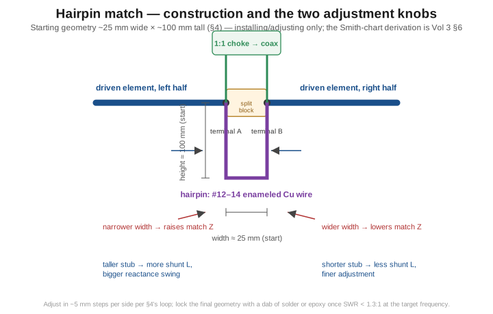
Start with a hairpin roughly 25 mm wide and 100 mm tall — a U-shaped bend in the #12–14 wire, both legs soldered to the two feed terminals, the closed end of the U pointing away from the boom. This is a starting point, not a target: published hairpin dimensions are design-specific and construction-tolerance-sensitive enough that no fixed number survives the trip from someone else’s build to yours unchanged. The two knobs available are independent enough to reason about separately, though real adjustment iterates both together in practice:
- Width sets how tightly the two hairpin legs couple to each other and to the driven-element terminals — narrower generally raises the match impedance the antenna sees, wider generally lowers it.
- Height (the stub’s length before it closes into the U) sets the amount of shunt inductance directly — taller adds more inductive reactance for the same starting capacitive offset to cancel, giving a bigger overall reactance swing at the cost of coarser control; shorter gives finer control over a smaller range.
Adjust in roughly 5 mm steps per side, re-sweeping after each change (§5’s workflow). Because width and height both move the match point along the same constant-conductance arc Vol 3 §6 plotted, there is more than one combination of the two that lands close to 50 Ω — the practical target is whichever combination gets there with the hairpin’s overall size staying mechanically reasonable (not so tall it flaps in the wind, not so narrow the two legs risk shorting under ice load). Once the sweep shows SWR below about 1.3:1 at the target frequency, the hairpin’s geometry is done; lock it with a dab of solder at the two bend points (to stop the wire creeping under thermal cycling) or a small bead of outdoor-rated epoxy, and don’t touch it again — unlike a gamma match, a properly adjusted hairpin has no field-serviceable capacitor to age or fail, which is the entire mechanical argument in its favor.
5.5 Tuning and verification with a NanoVNA
Calibrate at the feedpoint, every time. Run the standard OSL (Open-Short-Load) sequence at the coax connector you’ll actually sweep through — ideally right at the choke’s SO-239, or at the shack end of a known feedline if climbing to the antenna for every sweep isn’t practical, in which case remember that feedline’s own length and loss are now baked into every reading. A quick Smith-chart sanity check (open at the far right edge, short at the far left, load dead center) confirms the calibration before touching the antenna.
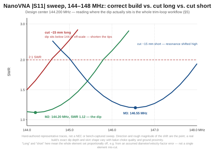
Sweep wider than you expect to need. 140–150 MHz is a comfortable first-pass span around a 144.2 MHz target — wide enough to catch the dip even if the whole antenna comes out further off-frequency than expected, which happens more often from a wrong assumption about element diameter or tubing alloy than from an actual cutting error. Read where the trace’s minimum actually sits, not what the SWR reads at 144.2 MHz specifically.
What “landed low” and “landed high” each mean. A Yagi’s driven element behaves like any half-wave radiator here: electrically too long resonates below target, too short resonates above it. Because the reflector and directors are all proportioned as percentages of the driven element’s length, a systematic diameter or material error scales the whole geometry together — the figure above shows exactly that, with the “cut long” trace’s dip sitting off the left edge of the window and the “cut short” trace’s dip sitting well above target on the right. A single element mis-cut in isolation reads differently — mostly as degraded F/B and a shallower, messier null rather than a clean shift — which is itself a useful diagnostic: a clean frequency shift with a still-deep null points at the driven element or a scaling error; a shallow, ragged null that won’t deepen no matter how the hairpin is adjusted points at a bent or mis-cut parasitic element instead.
Trim, and know which element actually moves the needle. The driven element’s length couples most directly to the feedpoint’s resonant frequency — if the whole antenna reads a few hundred kHz off in a clean, single-dip way, that’s the element to touch first, in small increments, re-sweeping after each cut. The reflector and directors are comparatively forgiving for this purpose — their job is phase-shaping via controlled detuning, not pinning an absolute resonance, so a millimeter or two off any one shows up as a fraction of a dB of gain or F/B degradation rather than a visible frequency shift. This is the honest answer to overall tolerance: on the order of ±2–3 mm (roughly a quarter of one percent) keeps the driven element’s resonant dip within a few hundred kHz of target — comfortably inside the 2 m band’s 4 MHz width — while gain and F/B degrade only a few tenths of a dB even with parasitic-element errors several times that size. That’s a defensible tolerance band, not the seed material’s unsupported ±1 mm claim; tight enough to justify a chop saw and stop block over a hand hacksaw, loose enough that a careful builder should succeed within one or two iterations.
What a good final sweep looks like. At minimum: SWR below about 1.5:1 across 144.0–145.0 MHz, below 2:1 across 144.0–146.0 MHz; the minimum landing within roughly 100–200 kHz of 144.2 MHz; a Smith-chart marker sitting close to the real axis with reactance near zero at the design frequency; and — the same fingerprint every antenna volume in this hub checks — no shift in the reading when the coax is flexed a meter or two below the choke. A sweep that moves when the feedline moves means common-mode current is riding the shield past an inadequate choke, which is a choke problem to fix (a few more turns, or a properly wound FT240-43 rather than an improvised substitute), not a length problem to trim around.
5.6 Commercial buys — ranked, with price tiers
For the builder who’d rather buy a factory-tuned reference — or wants a known-good antenna to sanity-check a homebrew build’s gain against — the following spans every Yagi product category this dive covers, checked against live manufacturer or dealer listings as of late July 2026.
Table 3 — 6. Commercial buys — ranked, with price tiers
| Category | Tier | Product | Specs | Price (late July 2026) | Notes |
|---|---|---|---|---|---|
| Portable/SOTA | Budget | Arrow Antennas 146-2 | 2-el, 2 m, hand-held | Not published on Arrow’s own site; typical dealer price is in the low-$100s | Lightest, cheapest Arrow model — modest gain, fastest deploy |
| Portable/SOTA | Budget | Arrow Antennas 146-3 | 3-el, 2 m, hand-held | Not published on Arrow’s own site — price could not be confirmed live this pass; treat any figure as an approximate dealer-market number, not a verified one | The long-running SOTA-favorite portable Yagi; Arrow’s current lineup (confirmed directly from arrowantennas.com) also includes 146-4, 440-3/-5/-7, and dual-band satellite crossed-Yagi models (146/437-10, 146/437-14 “Alaskan Arrow”) |
| Portable/SOTA (satellite) | Premium | M2 Antenna Systems LEO-Pack (436CP16 + 2MCP8A) | Cross-Yagi pair, 70 cm + 2 m, circular polarization | $723.99 (verified, m2inc.com) | A fixed-mount satellite array rather than a hand-held portable, but the premium tier’s answer to the same “point a beam at something moving” problem |
| VHF/UHF single-band | Budget | Diamond A144S5 (5-el 2 m) / A430S10 (10-el 70 cm) | Historically the budget-tier entry in this category | Availability could not be confirmed — both Ham Radio Outlet and GigaParts returned “item not found”/discontinued-style results on live lookup this pass; Diamond’s own site directs buyers to “authorized dealers” with no listed price | Treat this line item’s current market status as genuinely uncertain rather than assume it’s still a live SKU — the honest finding, not an omission |
| VHF/UHF single-band | Mid | M2 Antenna Systems 440-6SS (6-el 70 cm, 420–450 MHz) | 420–450 MHz coverage | $188.99 (verified, m2inc.com) | M2’s 70 cm workhorse |
| VHF/UHF single-band | Mid | M2 Antenna Systems 2M7X (7-el 2 m) | 2 m | $258.99 (verified, m2inc.com) | M2’s smallest current 2 m Yagi — there is no M2 5-element 2 m product in the live catalog |
| VHF/UHF single-band | Premium | M2 Antenna Systems 2M9X (9-el 2 m) | 2 m | $403.99 (verified, m2inc.com) | The 2 m step up from the 2M7X |
| VHF/UHF single-band | Premium | M2 Antenna Systems 456CP34 (34-el cross-Yagi, 435–470 MHz) | EME/satellite-class, circular polarization | Price not confirmed live this pass | Long-boom, specialized-application design |
| 2.4/5 GHz Wi-Fi | Budget | L-com HG2415Y-NF | 2.4 GHz, 15 dBi claimed, N-female, radome-enclosed | Price could not be confirmed live this pass (multiple fetch attempts failed); L-com’s catalog lists over 200 2.4 GHz antenna models, this being their standard 15 dBi Yagi | A real, legitimately-specified product — 15 dBi from a 12 in. radome-enclosed Yagi is a physically plausible claim, unlike the next line |
| 2.4/5 GHz Wi-Fi | Budget (avoid) | Generic unbranded “high-gain” 2.4 GHz Yagi | Claimed 25 dBi, ~51 cm (20 in.) length | Typically $20–40 on general marketplaces | A concrete example of the inflated-gain problem §8 discusses in general: a 20 in. Yagi at 2.4 GHz cannot physically deliver 25 dBi — the real figure for that aperture is closer to 12–15 dBi. The antenna itself likely works fine at its real gain; the number on the box is the lie |
| 2.4/5 GHz Wi-Fi | Premium | RF elements (rfelements.com) | Full 2.4/5 GHz line — Yagi, panel, sector, grid, dish | Specific model/price not confirmed live this pass | Industrial/WISP-grade catalog; worth naming as the professional-tier alternative to consumer Wi-Fi antenna listings |
| HF tribander/monobander | Budget-mid | Hy-Gain TH-3JRS | 3-el, 20/15/10 m, 5.8 dBd avg gain, 12 ft boom, 600 W PEP | Price not confirmed live this pass; historically in the $600–700 range across dealers | The long-running compact tribander for space-limited installations |
| HF tribander/monobander | Mid | M2 Antenna Systems 6M-3SS (3-el 6 m monobander) | 50–54 MHz | $374.95 (verified, RW Antennastore) | Secondary-retailer verification, not the manufacturer’s own site |
| HF tribander/monobander | Premium | M2 Antenna Systems 20M5LD (full-size 5-el 20 m monobander) | Contest/DX-grade | Price not confirmed live this pass | M2’s own copy describes it as built “for world-class competition and DXing” |
| HF tribander/monobander | Premium | OptiBeam (now under WiMo ownership as of June 2025) | Full HF monobander/tribander line, “Made in Germany” | Specific model/price not confirmed live this pass | Status update on a name that appears in older buy tables: OptiBeam is confirmed still active, sold today through WiMo and its usual dealer network including DX Engineering |
| HF tribander/monobander | Premium (lineage note) | Force 12 “Magnum” series — no longer a live product line under that name | — | — | Force 12, Inc. sold its product line in 2008 and no longer operates as an independent company; founder Tom Schiller (N6BT) now runs Next Generation Antennas (current models include the Q52 Yagi and the Bravo V8 vertical), while the Force12 brand itself passed to InnovAntennas in 2013 (operations relocating from Bridgeport, TX to Grand Junction, CO) before reaching JK Antennas, which now markets itself directly as “the new home of Force 12 Antennas.” The chain is two ownership changes, not one. Neither successor’s current pricing was confirmed live this pass — but the plain fact that “Force 12 Magnum 5/6” is not a company you can currently order from is worth knowing before chasing that exact name |
The M2 “7M9SSB, 7 m” correction. A product resembling “M2 Antennas 7M9SSB (9-el 7m)” appears in the migrated seed material this dive replaces. Checked directly against M2’s own current catalog (m2inc.com) rather than against the seed’s memory of it: M2’s 2 m line tops out at the 2M9X, their 70 cm line runs from the 440-6SS up through the 456CP34, and no 7 m product exists anywhere in their current lineup — for the simplest possible reason that there is no 7 m amateur allocation in the US band plan for M2 to be building a Yagi for. The seed’s entry was simply invented; this table lists what M2 actually sells instead.
What to avoid. Unbranded “high-gain” Wi-Fi Yagis whose dBi claim isn’t physically plausible for the antenna’s size — the table above gives a concrete worked example rather than a generic warning. Multi-band “miracle” Yagis sold with no published element geometry or spec sheet — every reputable manufacturer in this table publishes dimensions and gain figures, and a listing that won’t is hiding something. Used Yagis with visibly corroded element-to-boom joints, which introduce variable contact resistance that degrades pattern and F/B in ways an SWR meter alone won’t catch (§8). And, the market-condition finding this session turned up rather than assumed: a brand name from an older buy list — Force 12 among them — is worth a five-minute check that the company still exists before budgeting around its catalog price.
5.7 Companion gear — rotators, masts, coax, thrust bearings
Vol 4 owns the selection criteria for a rotator — wind load and turning moment, worked out from the specific antenna’s boom length and element count. This section is the ranked hardware survey those criteria get applied to, plus the mast, coax, and bearing hardware a Yagi installation depends on that Vol 4 didn’t need to cover.
5.7.1 Rotators
Table 4 — 7.1 Rotators
| Rotator | Class | Price (late July 2026) | Notes |
|---|---|---|---|
| Yaesu G-450A (current version: G-450ADC) | Light-duty | ≈ $429.95 (moderate confidence, GigaParts) | Rated for 10 sq ft wind load tower-mounted, 5 sq ft mast-mounted, 600 kgf-cm rotation torque, 3000 kgf-cm braking/stationary torque — the correct antenna for this volume’s own 5-element build. The current G-450ADC uses a 20 V DC four-wire motor and is not compatible with the older 26 VAC five-wire G-450 |
| Yaesu G-800SA | Medium-duty | Confirmed discontinued — no longer available new from GigaParts as of this check | Historically the step up for moderate HF tribanders or larger VHF arrays; the honest finding here is that this specific model is gone, not merely hard to find |
| Yaesu G-2800DXA | Medium-heavy | ≈ $1,769.95 (moderate confidence, Ham Radio Outlet, “after coupons”) | Digital-readout heavy VHF/light HF class — the right tier for the M2 2M9X or a small HF monobander |
| Prosistel PST-71D | Heavy/industrial | New price needs a current dealer quote — a used unit with controller sold at $2,875 on the secondary market (eHam classified), which is at least a real reference point | Rated for roughly 80 sq ft of wind load; the tier for large HF monobanders and EME-class VHF stacks |
5.7.2 Masts and towers
For VHF/UHF Yagis in this dive’s weight and wind-load class (a 5-element 2 m or 9-element 2 m beam), a 5–10 m telescoping aluminum mast or a short push-up fiberglass section is sufficient support — the full mast, guying, and tower-selection catalogue belongs to this hub’s dedicated mounting, masts, and towers volume, cited here rather than reproduced. For a long-boom HF monobander or a stacked VHF/UHF array, a proper guyed tower (the Rohn 25G family is the standard amateur reference point) becomes the realistic choice once wind load and boom length grow past what a mast alone can carry — Vol 4’s wind-load-and-torque framework is exactly what decides where that line falls for a specific antenna.
5.7.3 Coax and the loss budget at VHF/UHF
The single most consequential companion-gear decision for a VHF/UHF Yagi is the feedline: coax loss at 2 m and 70 cm is dramatically worse than the same cable’s loss at HF, a fact that gets less attention than it deserves because most builders’ feedline intuition is calibrated on HF numbers. Representative figures, drawn from the manufacturers’ own long-published (and stable, unlike pricing) attenuation specifications:
Table 5 — The single most consequential companion-gear decision for a VHF/UHF Yagi is the feedline: coax loss at 2 m and 70 cm is dramatically worse than the same cable's loss at HF, a fact that gets less attention than it deserves because most builders' feedline intuition is calibrated on HF numbers. Representative figures, drawn from the manufacturers' own long-published (and stable, unlike pricing) attenuation specifications
| Cable | Loss @ 150 MHz | Loss @ 450 MHz |
|---|---|---|
| RG-8X | ≈ 5.5–6.0 dB/100 ft | ≈ 10–12 dB/100 ft |
| LMR-400 | ≈ 3.9 dB/100 ft | ≈ 6.8 dB/100 ft |
| LMR-600 | ≈ 2.5 dB/100 ft | ≈ 4.4 dB/100 ft |
| 1/2 in. Heliax (LDF4-50A) | ≈ 1.3 dB/100 ft | ≈ 2.3 dB/100 ft |
The worked consequence is worth sitting with: 100 ft of RG-8X feeding a 9-element 2 m Yagi loses over half the transmitter’s power to the cable alone before it ever reaches the antenna, and the same run at 450 MHz is worse still, while the identical 100 ft in 1/2 in. Heliax loses under a decibel. This is why serious VHF/UHF stations run hardline or at minimum LMR-400-class cable for any run longer than a few tens of feet, where an HF station on the same RG-8X barely notices the difference — the loss-vs-frequency curve for any coax dielectric steepens with frequency, and 2 m/70 cm sits far enough up that curve that the “good enough” HF feedline choice quietly becomes the wrong one. The full transmission-line loss derivation lives in this hub’s foundational transmission-lines-and-feedlines volume, cited here rather than re-derived.
5.7.4 Thrust bearings and boom-to-mast hardware
For any Yagi heavier or longer-boomed than a light 5-element VHF beam, a separate thrust bearing between the boom-to-mast bracket and the rotator takes the antenna’s static weight and wind-induced bending moment off the rotator’s own drive shaft, which is rated for rotational torque, not for carrying a cantilevered load indefinitely. This session could not pin a specific current thrust-bearing SKU/price live; the category itself is standard (every rotator manufacturer and most tower-hardware suppliers sell a matched thrust bearing for their own mast-diameter range), and it belongs on any installation where the boom’s wind load and weight materially exceed what a light 5-element 2 m Yagi presents.
5.8 Gotchas and myths for the Yagi family
“A hairpin needs periodic field adjustment like a gamma match.” False, and this is the single biggest practical advantage the hairpin has over the gamma Vol 3 §4 covers: once locked with solder or epoxy after the §4 adjustment loop, a hairpin has no capacitor to age, corrode, or detune with temperature. A gamma match’s series capacitor is the part that actually needs re-checking over a Yagi’s service life; a hairpin, once right, stays right.
“Grounding the parasitic elements to the boom ruins the pattern.” False, and this volume’s own construction sequence (§3) deliberately does exactly that for the reflector and both directors. DL6WU- and K1FO-style designs are routinely built this way in the field — the boom-grounding effect on each element’s effective length is a small, well-characterized correction, not a design flaw, and it’s exactly why this build’s element lengths are dimensioned for a boom-grounded mount rather than an insulated one. The one element that must never be grounded is the driven element, because it’s the one actually carrying the feed.
“Any UHF connector pair is fine at any frequency a Yagi operates at.” The venerable SO-239/PL-259 pair is not a constant-impedance connector, and its mismatch contribution grows with frequency — genuinely negligible at HF, small but present at 2 m, and worth moving away from (toward N-type or better) as the design frequency climbs into 70 cm and above, especially on a Wi-Fi-band Yagi where an N connector is the de facto standard for exactly this reason.
“The rotator’s torque rating tells you if it’ll survive a storm.” A rotator datasheet publishes at least two torque figures, and they answer different questions: rotation torque (how much twisting force the motor can deliver while actively turning — 600 kgf-cm for the Yaesu G-450A verified in §7) and braking/stationary torque (how much the parked rotator can resist before slipping while a gust loads the antenna — 3000 kgf-cm for the same unit, five times higher). Sizing a rotator against an antenna’s static wind load and checking only the rotation-torque number is checking the wrong figure; the braking torque is what determines whether a beam survives a gust while parked pointed into it.
“SWR under 1.5:1 means the whole Yagi is performing correctly.” A clean SWR sweep confirms the feedpoint match — it says nothing about forward gain, front-to-back ratio, or pattern symmetry. A bent director, an element shorted to a supposedly-grounded boom section in the wrong place, or a nearby mast leg sitting inside the near field can each degrade gain and F/B by several dB while the SWR trace looks perfectly healthy, since none of those faults necessarily move the feedpoint impedance much. Comparing received signal strength against a known reference antenna, or rotating the beam through 360° and confirming the F/B null shows up where predicted, catches what an SWR sweep alone cannot.
“Mount it wherever there’s a convenient bolt-hole on the tower.” A Yagi’s near-field extends far enough that a nearby tower leg, another antenna’s boom, or a guy wire close to the reflector or a director can detune that element and skew the pattern asymmetrically. The practical fix is the one §3 already flags — confirm the sweep looks consistent at a couple of rotational offsets before finalizing the mount — and, where geometry allows, keep the boom’s ends at least a wavelength clear of large parallel conductors.
“Fatter elements need 10–20% less length for the same resonance.” This is the specific wrong figure the migrated seed material for this dive states, and it’s worth naming exactly so it doesn’t quietly resurface: Vol 1 §8 already resolved this properly — the diameter correction is not a fixed percentage at all, it’s a function of the element’s length-to-diameter ratio, and for the tubing sizes typical of HF/VHF amateur construction it comes out on the order of 1%, not 10–20%; corrections that large only show up at UHF and microwave frequencies where an element’s diameter becomes a genuinely substantial fraction of a wavelength. This volume’s own element substitution in §2 (5/8 in. tubing standing in for a 1/2 in.-designed geometry) is a live, worked example of that same 1%-scale correction in practice, not the seed’s fictional 10–20% one.
5.9 Where this volume — and this dive — hands off
This volume closed the Yagi-Uda dive by putting the first four volumes’ theory on a boom. It gave a complete, real-parts bill of materials and construction sequence for a 5-element 144.2 MHz build — a verified $139.95 in DX Engineering element tubing (with the honest arithmetic showing why all five elements need separate stock, not three) and a real total of roughly $255–300 that the BOM table itself supports rather than contradicts — while keeping the seed’s honest hedge about this design’s K1FO-style (not verbatim K1FO) provenance. It gave the hairpin match an installation-and-adjustment procedure grounded in Vol 3’s own derivation of what the match is actually doing, and a NanoVNA workflow with an honestly-scoped tolerance figure (±2–3 mm on the driven element) in place of the seed’s unsupported ±1 mm claim. It surveyed the commercial market across four Yagi-family product categories, retired a fabricated seed entry (M2’s nonexistent “7 m” Yagi), and turned up a real market-condition finding along the way — Force 12’s actual 2008 sale and current successor brands. And it closed with the companion hardware and the myths that separate a Yagi that performs for a decade from one that reads fine on an SWR meter and is quietly wrong anyway.
Zooming out, this volume is also the last of the five that make up the Yagi-Uda dive. Vol 1 derived the parasitic-array principle — reactance sign into current phase, current phase plus geometric spacing into forward gain and a rear null — along with the honestly-researched 1926 Tohoku history and the resolved element-diameter correction this volume leaned on directly. Vol 2 took ownership of the design space: boom length versus gain, and the three-way tension between peak gain, F/B, and bandwidth that DL6WU, K1FO, LFA, and OWA each represent a different point on. Vol 3 worked through the feedpoint-impedance problem parasitic loading creates and the five matching topologies that solve it, down to the Smith-chart mechanics this volume’s §4 only had to install. Vol 4 covered the radiation pattern, SWR curve, deployment scenarios, power handling, and the rotator-selection criteria this volume’s §7 turned into a priced hardware survey. And this volume put all of it on a cutting list, a NanoVNA, and a dated shopping list.
The Yagi-Uda is this hub’s canonical answer to “I know which direction I want gain,” and the DIY-and-buy pattern this volume closes with — real BOM, real construction sequence, real tuning workflow, honestly-flagged gaps — is the template this hub’s other antenna-family dives carry forward on their own geometry. The matching-network theory this dive touched at its edges lives in this hub’s BALUNs and UNUNs dive; the measurement theory behind §5’s NanoVNA workflow lives in this hub’s NanoVNA deep dive; and the NEC modeling that turns any Yagi geometry into a performance prediction before metal gets cut lives in this hub’s antenna modeling software dive. This volume points to each rather than reproducing them.
5.10 Resources
- ARRL Antenna Book (25th+ ed.), the Yagi-Uda design chapter and its supplemental design-file collection — the canonical amateur reference for K1FO’s actual published 144 MHz designs (K1FO-12/16/22/33) and the source this volume repeatedly tells the reader to cross-check dimensions against.
- Powlishen, K1FO, “An Optimum Design for 432 MHz Yagis”, QST, December 1987 and January 1988 (two-part series) — Powlishen’s own canonical published Yagi work, EME-class long-boom designs rather than the compact 5-element form this volume built.
- DX Engineering — https://www.dxengineering.com — the source verified live for the element tubing part number and price in §2.
- M2 Antenna Systems — https://www.m2inc.com — the source verified live for the current 2 m, 70 cm, and 6 m Yagi lineup and prices in §6, and the source that settled the seed material’s fabricated “7 m” product.
- Fair-Rite Products ferrite datasheets (mix 43) — the reference for the VHF/UHF choke core material specified in §2; the broader mix-31-vs-43 selection rationale lives in this hub’s BALUNs and UNUNs dive.
- Nooelec — https://www.nooelec.com — the source verified for the NanoVNA-H4 specification and price, now confirmed at the identical figure across three DIY volumes in this hub.
- NanoVNA-Saver (PC companion software) — https://github.com/NanoVNA-Saver/nanovna-saver — free, and the natural next step once §5’s on-device sweep confirms the build is converged; it logs and overlays sweeps, the easiest way to compare a first-pass and a final trace like the ones in this volume’s figure.
- Times Microwave Systems coax attenuation datasheets (LMR-400, LMR-600) and CommScope/Andrew Heliax datasheets (LDF4-50A) — the long-published, stable attenuation figures behind §7’s VHF/UHF coax loss table.
- This hub’s NanoVNA deep dive — the full instrument-level treatment behind the workflow §5 used at the level this volume needed.
- This hub’s BALUNs and UNUNs dive — the full ferrite-mix, winding, and common-mode-choke theory behind the 1:1 choke this build installed without re-deriving.
- This hub’s antenna modeling software dive — NEC-2/NEC-4 and 4nec2, the tools that let a builder verify a K1FO-style geometry’s actual gain, F/B, and bandwidth before committing to a cutting list.
Comments (0)