Satellite Antennas & Rotators · Volume 4
Microwave: The Dish, the LNB and the Chain Behind the Antenna
Why ten gigahertz has no feedline at all, a dish the seed chapter says has almost no gain and which has 14.8 dBi, a preamplifier at the radio that is worth 5.4 dB rather than nothing, and a motionless satellite that still drifts
4.1 About this volume
Vol 2 and Vol 3 covered antennas that can be built from rod, tube and coax. This volume covers the bands where that stops working, and where the antenna is the least interesting part of the antenna system.
The organising fact is one number. At 10 GHz there is no practical coaxial feedline, so the first active device sits at the focus of the dish, and everything behind it travels at an intermediate frequency. That single constraint restructures the station: the “antenna” becomes a reflector, a feed, a downconverter and a bias tee, and the questions that decide whether it works are about noise figure and oscillator stability rather than about element lengths.
Three findings differ from the seed chapter, and two of them are corrections to warnings that are sound advice attached to wrong numbers.
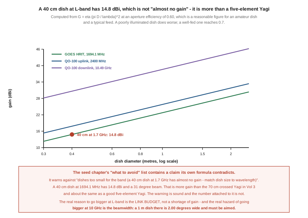
A 40 cm dish at L-band does not have “almost no gain”. §3 computes it: 14.8 dBi, which is more than the 70 cm crossed Yagi in Vol 3 and about what a good five-element Yagi manages. The seed’s warning against undersized dishes is correct and its justification is not, and the real hazard at these frequencies turns out to be the opposite one — a 1 m dish at 10 GHz has a 2.0 degree beam and has to be aimed properly.
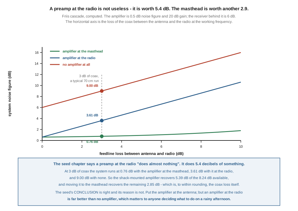
A preamplifier at the radio does not “do almost nothing”. §8 computes the Friis cascade: with 3 dB of coax it takes the system from 9.00 dB noise figure to 3.61 dB, a recovery of 5.39 dB. Moving it to the masthead recovers a further 2.85 dB. The seed’s conclusion — put the amplifier at the antenna — is right and worth keeping; its reasoning would tell an operator with an indoor preamplifier and no mast access that there is no point fitting it, which is wrong by more than five decibels.
And a geostationary satellite with no Doppler shift at all still needs a disciplined oscillator. §5 works it. The LNB’s local oscillator sits at 9,750 MHz, so one part per million is 9.75 kHz, which is 3.6 times the entire width of an SSB channel. A stock television LNB at 10 ppm drifts 97.5 kHz — thirty-six channel widths. The instability is wholly local, and the seed chapter states this correctly without quantifying how brutal it is.
4.2 Ten gigahertz has no feedline
The satellite rule Vol 1 §8 established — put the gain ahead of the loss and keep the run short — has a limit, and at 10 GHz it is reached absolutely rather than economically.
Coaxial loss rises with frequency roughly as its square root for a given cable, and the cables that carry 10 GHz at all are semi-rigid or waveguide. A run of ordinary coax at 10.5 GHz throws away tens of decibels in tens of metres. There is no cable answer and no budget for one, because Vol 1 §8’s link has single-figure margins.
The resolution is the low-noise block downconverter: a receive converter mounted at the dish’s focus, containing the low-noise amplifier, a local oscillator and a mixer, which delivers an intermediate frequency low enough to travel ordinary coax. For the universal Ku-band LNB the low-band local oscillator is 9,750 MHz, so a 10,489.75 MHz signal arrives at the radio as 739.75 MHz — a frequency at which LMR-400 is entirely reasonable.
Three consequences follow, and they are the architecture of every 10 GHz station.
The first active device is outdoors, and there is no choice about it. §8’s whole discussion of where to put the preamplifier does not arise at 10 GHz: it is at the feed, because the alternative does not exist. The masthead-versus-shack argument is a VHF and UHF argument.
One cable does three jobs. The coax carries the intermediate frequency down, the LNB’s DC supply up — 12 to 14 V through a bias tee — and, on some LNBs, a reference signal. That is why a QO-100 receive chain has so few parts: dish, feed, LNB, bias tee, receiver.
And the local oscillator becomes a component of the receiver. Its stability is added directly to the signal’s frequency, one for one, and §5 is about what that costs.
4.3 The dish, and a warning attached to the wrong number
A parabolic reflector’s gain is aperture arithmetic:
G = η · (π D / λ)²
with η the aperture efficiency — the fraction of the geometric area the feed actually uses. The figures here take η = 0.60, which is a reasonable amateur number; a well-illuminated dish reaches 0.7 and a badly-fed one considerably less. The beamwidth follows the usual 70 λ / D degrees.
Table 1 — 3. The dish, and a warning attached to the wrong number
| diameter | 1694.1 MHz (GOES) | 2400 MHz (QO-100 up) | 10.49 GHz (QO-100 down) |
|---|---|---|---|
| 0.4 m | 14.8 dBi, 31.0° | 17.8 dBi, 21.9° | 30.6 dBi, 5.00° |
| 0.6 m | 18.3 dBi, 20.7° | 21.4 dBi, 14.6° | 34.2 dBi, 3.33° |
| 1.0 m | 22.8 dBi, 12.4° | 25.8 dBi, 8.7° | 38.6 dBi, 2.00° |
🔴 The seed chapter’s “what to avoid” list contains a claim its own formula contradicts. It warns against “dishes too small for the band (a 40 cm dish at 1.7 GHz has almost no gain — match dish size to wavelength)”. A 40 cm dish at 1694.1 MHz has 14.8 dBi and a 31-degree beam. That is more gain than the 13.3 dBic crossed Yagi Vol 3 priced at $367.95, and about what a good five-element Yagi delivers. It is not “almost no gain”; it is a respectable antenna.
⚠ The advice is nevertheless sound, and it is worth being precise about why, because the correct reason is more useful than the wrong one. The reason to use a bigger dish for GOES is not that a small one has no gain. It is that the link has a hard demodulation threshold (Vol 3 §2), so the question is not “is there gain” but “is there enough”, and the answer comes from the budget rather than from the antenna. A 40 cm dish is a real antenna that may still be several decibels short of what the downlink needs.
⭐ And the real hazard at these frequencies is the opposite of the one the seed warns about. Read the beamwidth column. A 1 m dish at the QO-100 downlink frequency has a 2.00 degree beam. That is narrower than the pointing accuracy of a great many mounts, narrower than the amount a mast twists in wind, and narrow enough that an installation aimed by eye will miss. Going bigger at 10 GHz buys gain and spends pointing tolerance, and past about a metre the pointing becomes the harder problem. Vol 5’s discussion of mechanical stability is about tracked LEO arrays, but a bolted-down 10 GHz dish has a stricter requirement than most tracked antennas do.
The same reading explains the community-standard QO-100 receive dish. A 60 cm offset dish gives 34.2 dBi with a 3.3 degree beam: enough gain for the transponder and a beam wide enough to find and hold by hand. That is not a compromise — it is the optimum of two opposing constraints.
4.4 QO-100, and the numbers that define the chain
QO-100 is the amateur transponder aboard Es’hail-2, in geostationary orbit at 26° East. Because it is geostationary it sits at one fixed azimuth and elevation from any ground station: aimed once, bolted down, no rotator, no tracking, no keyhole. Everything Vol 5 discusses is irrelevant to it, and everything §5 discusses is not.
Table 2 — 4. QO-100, and the numbers that define the chain
| uplink | downlink | width | |
|---|---|---|---|
| narrowband transponder | 2400.00–2400.50 MHz | 10489.50–10490.00 MHz | 500 kHz |
| wideband transponder | 2401.50–2409.50 MHz | 10491–10499 MHz | 8 MHz |
⭐ The narrowband transponder is 500 kHz wide, and that number is the one to hold on to, because §5’s oscillator drift is measured against it and against the 2.7 kHz channels inside it.
4.4.1 The receive chain
Through a 9,750 MHz local oscillator the narrowband downlink appears at 739.50 to 740.00 MHz. The seed chapter says “a ~739 MHz IF”, which is correct; the exact figures are worth having because they are what a receiver is configured with.
The chain is short: offset dish → feed → LNB → coax → bias tee → receiver. The bias tee injects 12–14 V up the same cable that brings the intermediate frequency down. A general-coverage SDR covers 739 MHz without difficulty.
The seed chapter recommends a 60–100 cm offset dish, and §3’s table supports it: 34.2 to 38.6 dBi, with beamwidths from 3.33 down to 2.00 degrees. ⚠ The upper end of that range is where the pointing problem starts, and the seed does not say so.
4.4.2 The transmit side
The 2.4 GHz uplink is a transmitting problem rather than an antenna-geometry one, and this dive keeps it brief. The usual arrangements are a separate small dish, a dual-band feed sharing one reflector, or two co-pointed dishes. §3’s table gives the uplink numbers: a 60 cm dish at 2400 MHz is 21.4 dBi with a 14.6 degree beam — note that the same reflector has a beam four times wider on the uplink than on the downlink, which is why a dual-band feed’s alignment is set by the 10 GHz side.
⚠ Uplink power, EIRP and the Part 97 framing are outside this volume. The relevant point for the antenna is that a dual-band feed makes the transmit path share the receive path’s aiming, and a separate dish does not.
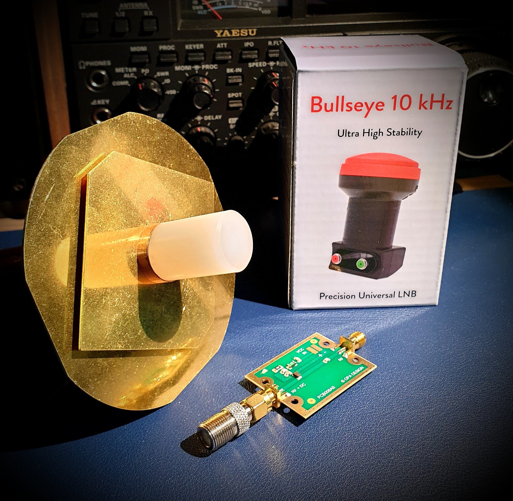
⚠ The photograph above illustrates the parts and not the installation, and the provenance file records why. The seed captioned it as a mounted offset dish aimed at the geostationary slot; there is no dish in the frame, nothing is mounted, and the LNB is inside its box. The components are exactly right, which is why it has been kept and re-captioned rather than dropped.
⚠ The dual-band feed shown is of a well-known amateur pattern — a 2.4 GHz patch combined with a 10 GHz waveguide aperture using a PTFE dielectric insert, so that one feed serves both bands on one reflector. This dive does not name its designer: the design is widely attributed in the community, and no source attributing it could be verified on 17 September 2026.
4.5 A motionless satellite that drifts anyway
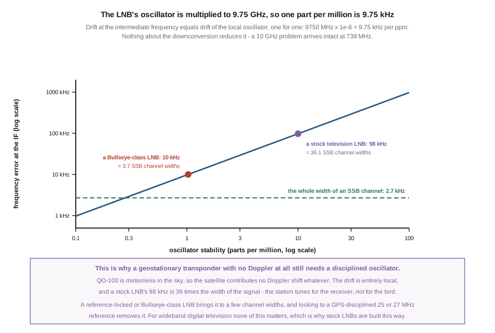
Nothing about downconversion reduces a frequency error. If the local oscillator moves by Δf, the intermediate frequency moves by exactly Δf — a 10 GHz problem arrives intact at 739 MHz. And because the local oscillator is at 9,750 MHz, fractional stability multiplies into a large absolute number:
Table 3 — Nothing about downconversion reduces a frequency error. If the local oscillator moves by Δf, the intermediate frequency moves by exactly Δf — a 10 GHz problem arrives intact at 739 MHz. And because the local oscillator is at 9,750 MHz, fractional stability multiplies into a large absolute number
| oscillator stability | drift at the IF | in SSB channel widths |
|---|---|---|
| 0.1 ppm (a good GPS-disciplined reference) | 0.98 kHz | 0.4 |
| 1 ppm | 9.75 kHz | 3.6 |
| ~1.03 ppm (a Bullseye-class “10 kHz” LNB) | 10.0 kHz | 3.7 |
| 10 ppm (a stock television LNB) | 97.5 kHz | 36 |
| 100 ppm (a poor LNB across its temperature range) | 975 kHz | 361 |
⭐ This is why a satellite that is motionless in the sky still presents a tuning problem, and it is a genuinely counter-intuitive result worth stating plainly. QO-100 is geostationary. The satellite contributes no Doppler shift whatever — that is the entire appeal of a geostationary transponder and it is why pass prediction does not apply to it. All of the frequency instability in the link is local, generated in the operator’s own LNB, and a stock one generates ninety-seven kilohertz of it: nearly a fifth of the whole narrowband transponder, and thirty-six times the width of the signal being received.
For wideband digital television — the job these LNBs are built for — none of this matters, which is why they are built this way and why they are cheap. For narrowband SSB and CW it is fatal: the station spends the contact chasing its own receiver rather than the other operator.
The seed chapter states the problem correctly: “a stock TV LNB drifts tens of kHz, which is invisible for wideband TV but fatal for narrowband SSB/CW.” ⚠ “Tens of kHz” is right in kind and low by about a factor of three on a 10 ppm part; the computed figure is 97.5 kHz. The conclusion it draws is confirmed.
4.5.1 What to do about it
A stability-specified LNB. The Bullseye-class parts quote about 10 kHz total, which the table above puts at roughly 1.03 ppm and 3.7 channel widths. ⚠ That is a great improvement and it is not a lock. Three or four channel widths of drift still needs retuning during a long contact; the specification makes the station usable, not stationary.
A reference-locked LNB. A PLL LNB can be modified, or bought ready, to take an external 25 or 27 MHz reference in place of its own crystal. Driven from a GPS-disciplined oscillator this removes the local drift entirely, to whatever the reference achieves. This is what a station running narrow digital modes needs, and the seed chapter is right that “if you run SSB/CW on QO-100, the reference lock is not optional” — with the qualification that a Bullseye-class part is a reasonable intermediate step rather than a wrong answer.
⚠ Neither the Bullseye LNB’s current price nor its manufacturer’s own specification could be verified for this dive; the “10 kHz” figure is the widely-quoted one and is treated here as a claim rather than a measurement. §11 records that.
4.6 L-band weather, and a satellite in the wrong category
The GOES High Rate Information Transmission service broadcasts imagery on 1694.1 MHz, and receiving it in a back garden is among the most rewarding projects in this hub: full-disk Earth imagery from a dish, a low-noise amplifier and a software-defined radio.
GOES-19 has been the operational GOES-East since 7 April 2025, at 75.2° West, with GOES-16 held as a stored spare. ⚠ The seed chapter refers to “GOES-18/19” without distinguishing their roles, which was reasonable when it was written and is now worth stating: a reader in North America aims at GOES-19 in the east or GOES-18 in the west, and at a specific longitude in each case.
Because these are geostationary, the L-band weather dish is aimed once and bolted down — the same architecture as QO-100, at a sixth of the frequency, with §3’s beamwidth column correspondingly forgiving. A 1 m dish at 1694.1 MHz has a 12.4 degree beam, which can be aimed with a compass and an inclinometer.
🔴 One satellite in the seed chapter’s L-band list is in the wrong category, and the error is structural rather than a slip. The chapter groups “GOES / Himawari L-band” and elsewhere “GOES-18/19 (HRIT), Himawari, Metop” together, and then says the dish is “aimed once at the relevant geostationary GOES position (no tracking, like QO-100)”. GOES and Himawari are geostationary and that is right. Metop is not. The MetOp satellites are in polar low-earth orbit, so a Metop downlink is a moving target that requires exactly the tracking the sentence says is unnecessary — and at 1.7 GHz with a 12-degree beam, tracking it is a real az/el problem of the kind Vol 5 is about.
⭐ The distinction is the same one Vol 1 §2 drew and is worth restating: “L-band weather” is not one problem. A geostationary L-band downlink is a pointing-once problem dominated by link budget. A polar-orbiting L-band downlink is a tracking problem and a link-budget problem, and it is considerably harder than anything else in this dive. Putting them in one list with one recommendation produces the wrong hardware for one of them.
⚠ No current-status check on the MetOp series was performed for this dive. The category correction stands regardless of which spacecraft are presently operating: a polar orbiter cannot be received on a bolted-down dish.
4.7 L-band patches — the case for no gain at all
For the broad-beam L-band receive cases — Inmarsat and its AERO and STD-C services around 1.54 GHz, Iridium near 1.62 GHz, and GNSS at 1.575 GHz — the right antenna is a small right-hand circularly polarized patch, usually with an integral low-noise amplifier, aimed roughly upward and left alone.
This is Vol 1 §7’s argument applied in a new place, and it is worth making explicitly because a patch looks like a compromise and is not. These signals arrive from high in the sky across a wide arc — a geostationary Inmarsat from one bearing, an Iridium constellation from everywhere, a GNSS constellation from everywhere at once. An antenna with gain would have to be pointed, and for GNSS there is nothing to point at, since the receiver is using six or more satellites simultaneously in different directions. The correct antenna genuinely has no gain, deliberately, and its specification is pattern shape and axial ratio rather than gain.
Active GPS patches with integral amplifiers are commodity parts costing a few dollars, and purpose-built Inmarsat and Iridium patches with bias-tee-fed amplifiers are sold for exactly this hobby. All of them are powered up the coax, which makes §2’s bias tee the recurring component of this whole volume.
⚠ Everything in this section is receive-only and on non-amateur allocations. The standard framing applies: an Amateur Extra licence does not extend to these bands, and nothing here authorizes transmitting on them. The multi-radio “GPS exception” — its always-on, dedicated-antenna character — is the multi-radio shared-antenna material’s subject.
4.8 Where the preamplifier goes, computed
The lead figure sweeps the Friis noise cascade for a 0.5 dB, 20 dB-gain amplifier ahead of a 6 dB receiver, with a variable length of coax, in three arrangements.
Table 4 — 8. Where the preamplifier goes, computed
| feedline loss | amplifier at the masthead | amplifier at the radio | no amplifier |
|---|---|---|---|
| 0.5 dB | 0.63 dB | 1.11 dB | 6.50 dB |
| 1.0 dB | 0.65 dB | 1.61 dB | 7.00 dB |
| 2.0 dB | 0.70 dB | 2.61 dB | 8.00 dB |
| 3.0 dB | 0.76 dB | 3.61 dB | 9.00 dB |
| 6.0 dB | 1.04 dB | 6.61 dB | 12.00 dB |
| 10.0 dB | 1.79 dB | 10.61 dB | 16.00 dB |
🔴 The seed chapter says a preamplifier at the radio “does almost nothing”. It does 5.39 dB of something. At 3 dB of coax — a typical 70 cm run — the system goes from 9.00 dB noise figure with no amplifier to 3.61 dB with one at the radio. Against Vol 1 §8’s link budget, five and a half decibels is most of the difference between a fixed antenna and a 13.3 dBic crossed Yagi. Telling an operator who has an amplifier and no mast access that there is no point fitting it is expensive advice.
⭐ Two structural results fall out of the table, and both are more useful than the rule of thumb they replace.
The shack-mounted amplifier’s benefit is exactly 5.39 dB at every loss in the table. It does not degrade as the coax gets worse. The reason is that the amplifier is the last stage before the receiver either way, so what it buys is the difference between a 6 dB receiver and a 0.5 dB amplifier in front of it — a fixed quantity, independent of everything upstream.
And moving the amplifier to the masthead recovers, to within rounding, the feedline loss itself: 2.85 dB of the 3 dB run, 5.57 dB of the 6 dB run, 8.82 dB of the 10 dB run. That is the whole content of the masthead-preamp argument, stated as an identity rather than as folklore: an amplifier ahead of the loss saves the loss; an amplifier behind it does not.
⚠ So the seed’s conclusion is right and its reason is wrong, and the corrected version is more actionable. Put the amplifier at the antenna, because that recovers the feedline loss on top of the 5.4 dB. If it cannot go at the antenna, fit it at the radio anyway, because 5.4 dB is not nothing. And the worse the feedline, the more the masthead position is worth — which is the argument for spending on a masthead amplifier before spending on better coax.
⚠ Two caveats on the table’s inputs. The 6 dB receiver noise figure is representative of a general-coverage SDR and not of a good VHF transceiver, which will be better; a lower receiver noise figure shrinks the 5.39 dB proportionately. And all of it assumes the amplifier is not overloaded — an amplifier at the masthead has no preselection ahead of it, and its dynamic range rather than its noise figure is often what decides whether it helps, which is the finding the receive-only loops dive reached independently for a different antenna family.
4.9 The sequencer, and the failure it exists to prevent
Everything in §8 concerns a receive-only chain. On any station that also transmits, a masthead amplifier is a component with a short life expectancy unless something protects it.
The mechanism is simple and the consequence is total. A low-noise amplifier is built for signals in the picowatt region (Vol 1 §8: −100 to −122 dBm). A transmitter delivers watts. Any path from the transmitter into the amplifier’s input — through a relay that has not yet finished moving, or through the antenna itself on a full-duplex station — destroys the first transistor, usually on the first transmission.
A sequencer is a small controller that imposes an order on the transition. On going to transmit it first bypasses or powers down the amplifier, waits, then switches the antenna relay, waits, then keys the power amplifier, and finally unmutes the transmitter. On return to receive it does the reverse. The waits are tens of milliseconds and they are the whole point: a relay takes real time to move, and an unsequenced station keys into a relay that is still in flight.
⭐ The full-duplex satellite case adds a requirement that the terrestrial case does not have, and the seed chapter states it correctly. On a V/U or U/V bird the station transmits on one band while receiving on the other, simultaneously, from antennas a metre apart on the same boom. There is no transmit-receive switching to sequence, because both are live at once — and the downlink amplifier is exposed continuously to the uplink’s near-field radiation. Protection there is a matter of band-pass filtering ahead of the amplifier and physical separation, rather than of timing. A sequencer protects a single-band station; a full-duplex satellite station needs filters as well.
4.10 Feedline, band by band
The rule from Vol 1 §8, made concrete, and with §8’s arithmetic now available to make it quantitative rather than exhortative.
Table 5 — 10. Feedline, band by band
| band | practical feedline | the position |
|---|---|---|
| 2 m | LMR-400 or similar | comfortable; the amplifier is worth fitting but the cable is not the problem |
| 70 cm | LMR-400 minimum, kept short | §8’s 3 dB case; the masthead position is worth 2.85 dB |
| 23 cm | LMR-400 is already lossy | masthead amplifier effectively mandatory |
| L-band (1.7 GHz) | short runs of good cable only | amplifier at the feed, always |
| 10 GHz | there is none | §2: the LNB downconverts at the feed and only the IF travels coax |
⭐ §8 turns the last column into a decision rule rather than a list of adjectives. The masthead position is worth the feedline loss. So the question “should this station spend on better coax or on a masthead amplifier” has a general answer: the amplifier, first, because it recovers the whole loss rather than reducing it, and it does so for a fixed price whatever the run length. Better coax is then worth buying for the transmit path, which an amplifier does nothing for.
Loss-per-100-feet against frequency is the transmission-line material’s subject and is not reproduced here.
4.11 Building and buying, dated
Everything checked on 17 September 2026. Unverifiable figures are marked as such rather than filled in.
4.11.1 The QO-100 receive chain, which is the buildable one
The community-standard receive station is genuinely cheap for what it achieves, and the seed chapter is right to say so:
Table 6 — The community-standard receive station is genuinely cheap for what it achieves, and the seed chapter is right to say so
| part | specification | note |
|---|---|---|
| reflector | 60–100 cm offset dish | a recycled Ku-band television dish is the usual source; §3 gives 34.2–38.6 dBi |
| feed | a dual-band patch feed, or a separate 10 GHz feed horn | the dual-band type shares one reflector between uplink and downlink |
| LNB | a PLL LNB, stability-specified or reference-locked | §5 — this is the decision that matters |
| bias tee | 12–14 V, passing the IF | §2 |
| receiver | anything covering 739–740 MHz | an SDR is the usual choice |
The decision that matters is the LNB, and §5 puts it in order: a stock television LNB is unusable for narrowband work at roughly 36 channel widths of drift; a stability-specified part brings that to about 3.7; a reference-locked part driven from a disciplined oscillator removes it. ⚠ Prices for none of these could be verified for this dive.
⚠ An axial-mode helix is one of the standard feed options for a prime-focus dish at these frequencies, which ties Vol 3 §6 to this volume: a short helix at the focus delivers circular polarization straight into the reflector with no phasing network. Its design follows Vol 3 §8’s window, scaled to the band.
4.11.2 What could not be verified
🔴 The seed chapter’s microwave product rows are withdrawn rather than refreshed, on the same basis as Vol 2 §11. Its table lists a “Recycled Ku offset dish + Bullseye LNB” at “$40 dish + $40 LNB”, a “Helix (commercial, 70 cm / 23 cm)” at “$120–250”, and a “QO-100 dual-feed dish + reference-locked LNB + 2.4 GHz uplink” at “$300–800”. None of these could be checked: the Bullseye LNB’s vendor could not be reached, and no current retailer listing for any of them could be retrieved. ⚠ The orders of magnitude are consistent with everything else known about this equipment and are probably about right — that is why they are described here rather than deleted silently — but they are not verified figures and should not be quoted as of this date.
The dual-band feed’s designer could not be established. §4.
MetOp’s current status was not checked. §6 — the category correction does not depend on it.
4.11.3 What to avoid
The seed chapter’s three microwave warnings, with the mechanisms this volume has supplied:
- “Generic 10 GHz LNBs for narrowband QO-100 work where LO drift will defeat SSB.” ✅ Confirmed and quantified: §5 puts a stock part at 97.5 kHz, thirty-six SSB channel widths, on a satellite with no Doppler shift at all.
- “Dishes too small for the band.” ⚠ Sound advice, wrong number. §3: the 40 cm dish it dismisses has 14.8 dBi at L-band. The correct reason is the link budget’s threshold, not an absence of gain.
- “Preamp at the rig does almost nothing.” 🔴 Wrong by 5.39 dB, §8. The conclusion — amplifier at the antenna — survives; the reasoning does not.
To those, §3 adds one the seed does not have: at 10 GHz, beamwidth is the constraint that bites first. A 1 m dish has a 2.00 degree beam, and above about a metre the pointing accuracy of the mount, and its stability in wind, decide whether the extra aperture is realised at all.
4.12 Resources
- AMSAT-DL (amsat-dl.org) — the QO-100 narrowband and wideband transponder band plans quoted in §4.
- The Es’hail-2 orbital slot and transponder frequencies in §4 were read from the spacecraft’s own record on 17 September 2026.
- NOAA / NWS EMWIN (weather.gov/emwin) — the source of §6’s GOES HRIT frequency of 1694.1 MHz, read 17 September 2026.
- Paul Wade W1GHZ, Microwave Antenna Book, chapter 4 — parabolic dish illumination, edge taper and the efficiency figures behind §3’s
η = 0.60, and the G/T argument for why a satellite dish is optimised differently from a terrestrial one. - SatDump — the decoder for GOES HRIT and the other digital downlinks in §6.
- Vol 1 — the link budget §3 and §8 are both spent against, and the reason circular polarization at 10 GHz is bought for a different reason than at 2 m.
- Vol 3 — the axial-mode helix, which §11 notes is also a dish feed.
- Vol 5 — the mount, which §3 shows matters more at 10 GHz than the tracked-array case usually assumes.
- Active splitters, distribution amplifiers and preamps — masthead amplifiers and bias tees in general, of which §8 and §9 cover only the satellite-specific parts.
- Receive-only loops, Vol 4 — where this program established that an amplifier at the antenna is judged on dynamic range rather than on noise figure, which is §8’s caveat.
- Satellite tracking — Doppler, which §5 deliberately does not cover: the drift computed there is local and has nothing to do with the satellite’s motion, because QO-100 has none.
Comments (0)