Multi-Band Dipoles · Volume 3
Tuner-Fed All-Band — the Doublet, G5RV and ZS6BKW
Open-wire-fed doublets and why ladder line beats coax under high SWR; the G5RV's 102 ft flat-top and ~34 ft matching section, Varney's actual 20 m design intent, and the honest limits of the 'all-band' claim; Brian Austin's ZS6BKW re-optimization and the engineering trade it makes to buy a genuine no-tuner match on more bands
3.1 About this volume
Vol 1 laid out the multi-band wire-antenna problem — a resonant half-wave dipole is single-band by construction, and the community’s six structural answers each trade something away to cover more ground with one wire — and worked through the off-center-fed dipole in detail, the “shift the feedpoint” answer that dominates the modern residential installation. Vol 2 took the “parallel resonators” and “series LC traps” answers: the fan dipole and the trap dipole, both of which keep the feedpoint centered and instead multiply or gate the resonant structure itself.
This volume takes the fourth and fifth rows of Vol 1’s table — the high-impedance feed and the compromise-length approaches — and gives them the depth they deserve, because they are the two designs an Extra-class operator is most likely to actually build if the goal is “the most bands off one wire, with the fewest structural gymnastics.” All three antennas treated here — the doublet, the G5RV, and the ZS6BKW — share a single defining trait that separates them from everything in Vol 1 and Vol 2: none of them tries to present 50 Ω to coax at the antenna. They all hand the matching problem to a tuner (or, in the G5RV/ZS6BKW case, to a length of reactive balanced line acting as a transformer plus a tuner on most bands), and they buy their multi-band coverage by tolerating — even embracing — an antenna impedance that would be a non-starter for a coax-fed design.
The three differ in how far they lean into that philosophy. The doublet leans in completely: it makes no attempt at a resonant or even approximately-matched geometry on any band, accepts whatever wild impedance swing the wire presents, and relies entirely on a balanced tuner to clean it up every time you change bands. The G5RV and ZS6BKW split the difference: a fixed length of balanced line does part of the matching work as a hard-wired transformer, tuned (by the original designers) to land somewhere tuner-friendly on as many bands as the geometry allows, and a tuner mops up whatever the transformer doesn’t fix. That distinction — full delegation to a tuner versus a partially pre-matched compromise — is what this volume is organized around, and it is also where the most persistent myth in the wire-antenna hobby lives: the belief that the G5RV is genuinely “all-band.” Section 4 takes that claim apart with real numbers.
A scope note before starting: this volume owns the feed philosophy and geometry of these three designs — why ladder line survives the SWR these antennas produce, what the G5RV’s matching section is actually doing electrically, and what Brian Austin changed to do better. It does not re-derive BALUN/UNUN theory (the hub’s dedicated matching-network dive owns that), nor tuner topology and Smith-chart matching mechanics (the hub’s antenna-tuner dive owns that) — both are cited rather than reproduced. Vol 4 picks up the linked dipole and the cage dipole, the two remaining entries from Vol 1’s table, along with the full best-case/worst-case matrix and power-handling comparison across the whole multi-band family. Vol 5 carries the DIY build (a Buckmaster-style OCFD, per Vol 1) and the commercial-buy survey for the family as a whole, including the balanced tuners and ladder-line hardware this volume’s designs depend on.
3.2 The tuner-fed philosophy — why these three share a lane
Vol 1 framed the multi-band problem as: a dipole’s feedpoint impedance is well-behaved (73 Ω-ish) only very close to its design frequency, and climbs into hundreds or thousands of ohms — reactive, and swinging wildly with frequency — everywhere else. The OCFD, fan, and trap answers (Vol 1, Vol 2) all attack that problem at the antenna: reposition the feed, parallel up separate resonant structures, or gate the wire electrically so that at every operating frequency something in the system looks approximately like a well-behaved half-wave dipole feeding 50 Ω coax.
The doublet, G5RV, and ZS6BKW instead accept the wild impedance and move the matching problem to the shack end of the feedline, which only works if the feedline itself tolerates carrying power at whatever impedance and however awful an SWR the antenna happens to present that day. That is the crux of why these three designs are inseparable from balanced, low-loss line — coax, as Section 3.3 works out precisely, would burn away a large fraction of the transmitter’s power converting reflected energy into heat in its own dielectric before a tuner ever got a chance to do anything. Balanced open-wire or ladder line sidesteps that failure mode because its loss mechanism is overwhelmingly conductor resistance rather than dielectric dissipation, and conductor-resistance loss barely changes with SWR. That single fact is why “feed it with ladder line into a tuner” is a coherent multi-band strategy at all, and it is the thread that runs through every section of this volume.
The three designs then differ only in how much of the matching job the fixed geometry does before the tuner gets involved, which is exactly a build-cost/operating-convenience trade:
Table 1 — The three designs then differ only in how much of the matching job the fixed geometry does before the tuner gets involved, which is exactly a build-cost/operating-convenience trade
| Design | What’s fixed | What the tuner still has to do | Where it sits |
|---|---|---|---|
| Doublet | Wire length only (loosely) | Everything, every band, every time | Maximum flexibility, maximum tuner reliance |
| G5RV | Wire length (102 ft) + matching-section length (~34 ft), tuned for 20 m | Matching on 6 of 7 other HF bands | Partial pre-match on one band |
| ZS6BKW | Wire length (93 ft) + matching-section length (~40 ft), tuned for a broader spread | Matching on only 3 of 8 bands | Partial pre-match on five bands |
Reading down that table is reading a single engineering lever being pulled progressively harder: the more careful the choice of flat-top and matching-section lengths, the more of the tuner’s job gets done for free by geometry, and the fewer bands genuinely need the tuner’s help. The doublet pulls that lever not at all — deliberately, because doing so buys it a wire length that is nearly arbitrary and a design that never needs re-deriving for a new band plan. The G5RV pulls it once, for one band. The ZS6BKW pulls it as hard as a 1980s-vintage Smith-chart-and-computer optimization could manage, for five.
3.3 The doublet — open-wire-fed, genuinely all-band
3.3.1 The non-resonant premise
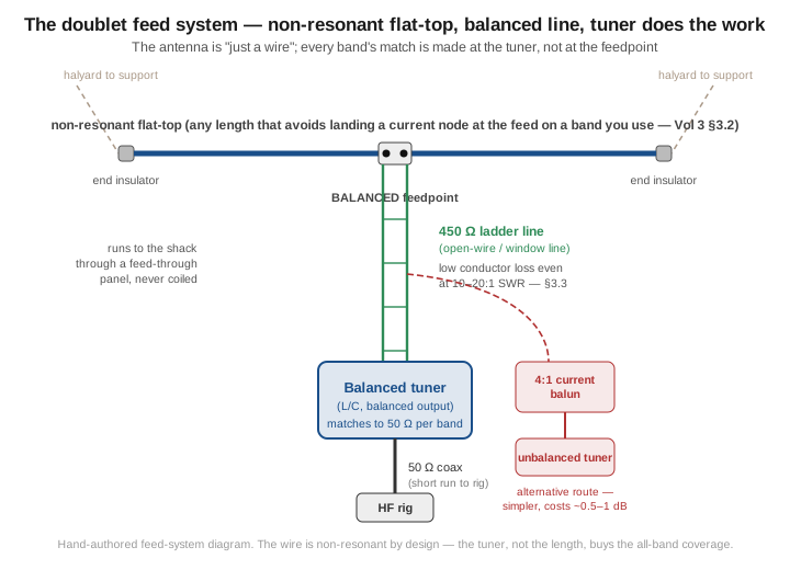
A doublet is the purest expression of the tuner-fed philosophy: a center-fed horizontal (or inverted-V) wire of essentially any convenient length, fed at the center with balanced open-wire or ladder line that runs all the way into the shack to a balanced antenna tuner. There is no attempt anywhere in the design to make the wire resonant, or even close to resonant, on any particular band. The antenna is, quite literally, “just a wire” — every bit of the matching intelligence lives in the tuner, and the tuner is expected to re-solve the matching problem from scratch every time you change bands.
That design freedom is real but not unlimited, and Section 3.2 works through the one geometric constraint that does matter. Once that constraint is respected, the doublet is the multi-band wire antenna with the fewest structural compromises in this entire dive: no traps to dissipate power, no BALUN forced to hold a fixed ratio across a 10:1 frequency span while carrying reflected power from a mismatched line, and no off-center feed asymmetry to distort the pattern. Every watt that reaches the antenna radiates as a clean center-fed dipole would, band by band — the price is paid entirely in feedline mechanics and shack-end hardware, not in the antenna’s electrical behavior.
3.3.2 Choosing a length — avoiding a current node at the feed
The doublet’s length does not need to be resonant on any band, but it is not a completely free parameter either, and the reason is worth working through because it is the single most common point of confusion in doublet design. A center-fed wire of physical length L supports an open-ended standing wave, with a current null forced at each open end. Whether the center — the feedpoint — lands on a current maximum (an antinode) or a current minimum (a node) as L sweeps through multiples of a half-wavelength depends on parity: at an odd multiple of λ/2 (one half-wave, three half-waves, five half-waves — the classic resonant dipole and its odd harmonics), the center is a current antinode, and the feedpoint impedance there is comparatively low and easy for a balanced tuner to reach. At an even multiple of λ/2 — i.e. the antenna is an integer number of full wavelengths on that band — the center falls on a current node, a voltage antinode, and the feedpoint impedance spikes to a very high, sharply reactive value. That combination — very high impedance at the antenna, further transformed (and sometimes inverted) by whatever length of ladder line stands between the antenna and the tuner — is what occasionally pushes the match outside even a good balanced tuner’s range, or drives the tuner’s internal voltages and currents uncomfortably high at legal-limit power.
The practical guidance that follows, echoed throughout the ARRL Antenna Book’s doublet-length treatment and the amateur literature surveying doublet dimensions (the W4RNL/Cebik doublet-length surveys are the deepest single source), is to pick a total flat-top length that does not land you exactly on a full-wavelength resonance — a current node at the feed — on a band you intend to use heavily, and, ideally, one whose ladder-line length also avoids landing near an odd multiple of a quarter-wavelength on that band (a quarter-wave-long balanced line inverts whatever impedance it’s given, Z_in = Z0²/Z_load, and combining a spike in antenna impedance with a length-driven inversion is the failure mode that occasionally defeats a tuner). Commonly cited practical lengths in the amateur literature include the 88 ft and 130–135 ft families of doublets — though the deeper reason these lengths endure is less that they dodge unfavorable resonances (a 135 ft doublet in fact sits near a current-node condition on several bands) and more that low-loss ladder line into a balanced tuner tolerates the resulting high feedpoint impedance and SWR without the loss penalty coax would incur. Treat those specific numbers as illustrative starting points from the literature rather than a rigid universal law — the underlying principle (avoid a length that puts a current node at the feed on a band you care about, and check the resulting geometry with a model or a tuner-range check before committing to a permanent installation) is the part that generalizes.
3.3.3 Why ladder line, not coax — loss under high SWR
The doublet’s entire feasibility rests on one number: how much power a mismatched feedline throws away as heat before the tuner even sees it. Coaxial cable’s published loss figures are specified for a matched (1:1 SWR) load, and that number climbs sharply as SWR rises, because coax loses energy in two ways — conductor resistance (which barely cares about SWR) and dielectric dissipation in the solid polyethylene or PVC insulation between the conductors (which scales with the standing-wave voltage and current peaks that a high SWR creates along the line). At 10:1 SWR, a coax with a nominally low matched loss can see its effective loss roughly triple, because the standing wave repeatedly drives the line’s peak voltage and current well above the matched-load values at successive points along its length, and the dielectric pays for every one of those excursions.
Open-wire and window (ladder) line sidestep that failure mode almost entirely, for the simple reason that there is very little dielectric in the loss path — the conductors are held apart mostly by air, with only small plastic spacers or a thin window-line web carrying any of the field. The dominant loss mechanism in ladder line is conductor (I²R) resistance, and conductor loss is nearly independent of SWR — the same total power flows through the same conductor regardless of how it’s distributed into forward and reflected waves. The result, well documented in the ARRL Antenna Book’s transmission-line chapter and in the amateur-literature ladder-line loss surveys, is that 450 Ω ladder line’s power loss at high SWR is typically an order of magnitude below a comparable-size coax’s loss at the same SWR — window line run at 9:1 SWR loses only a few percent of the applied power per hundred feet across most of HF, a fraction of what a coax carrying the same mismatch would dissipate. That gap is the reason the tuner-fed philosophy of Section 2 is viable at all: put a doublet’s wildly-varying, frequently-high-SWR load on ladder line, and the line itself barely notices; put the same load on coax, and the coax becomes a significant, band-dependent power-eating resistor standing between the rig and the antenna.
The corollary worth internalizing is that the advantage belongs to low conductor loss, not specifically to high characteristic impedance. Switching from 50 Ω coax to 450 Ω ladder line helps because the ladder line is an air-dielectric, large-conductor-spacing design with inherently low conductor resistance per unit length — the high Z0 is a consequence of that geometry, not the cause of the loss advantage. This distinction matters because it correctly predicts that a hypothetical 50 Ω open-wire line would show much the same high-SWR loss advantage over coax that 450 Ω ladder line does — the impedance number is incidental; the dielectric-versus-conductor loss split is what counts.
3.3.4 The balanced tuner (or 4:1 balun + tuner)
Because the ladder line delivers whatever the antenna presents — a raw impedance that might be a few ohms on one band and several thousand, heavily reactive, on the next — the device at the shack end has to be able to match across that entire range while staying balanced, since the line itself is balanced and any unbalanced load forces common-mode current onto the line (the same failure mode Vol 2’s BALUN discussion flagged for a coax-fed OCFD, here showing up on the doublet’s feeder instead). Two architectures handle this:
A genuine balanced tuner — an L-network or a differential-output pi/T design with balanced output terminals, such as the classic Johnson Matchbox or modern units like a Palstar AT2K or an LDG unit fitted with a balanced-line output — connects to the ladder line directly and does the whole matching job internally without ever converting to an unbalanced signal path. This is the cleanest architecture: no BALUN loss, no BALUN power rating to worry about, and no common-mode leakage from an imperfect impedance-ratio device.
The more common real-world compromise is an unbalanced (coax-input) tuner with a 4:1 (or sometimes 1:1) current BALUN inserted between the ladder line and the tuner’s coax input. This is simpler and cheaper — most hams already own an unbalanced tuner — but it costs something: the BALUN has to maintain its ratio across the same wide impedance swing the ladder line is delivering, and any deviation from the nominal ratio (which Vol 1’s OCFD BALUN discussion already flagged as a real-world ±25%-ish effect) shows up as an imperfect match and some BALUN heating, typically 0.5–1 dB of additional loss compared to a true balanced tuner. For a doublet fed at legal limit, the BALUN’s power rating needs headroom for the worst-case impedance the antenna can present across all the bands you intend to work, not just the nominal 50 Ω design case.
3.3.5 Pattern — donut-to-multilobe chaos on the higher bands
The doublet’s pattern behavior follows directly from its non-resonant, band-flexible length, and it is the price paid for the all-band flexibility. On the band where the flat-top happens to be close to a half-wavelength, the pattern is the familiar clean figure-8 broadside/end-null shape the single-band-dipoles dive develops in full. But because the same physical wire is reused, unchanged, on every HF band from 80 m through 10 m, on the higher bands the flat-top is several wavelengths long electrically — a 135 ft doublet is roughly 1.25 λ on 80 m but well over 4 λ on 10 m — and a long-wire radiator that many wavelengths long does not produce a simple figure-8. Instead, as each additional half-wavelength of current distribution is added along the wire, the far-field integral picks up additional in-phase and out-of-phase contributions at different angles, and the pattern fragments into multiple main lobes, generally squeezed closer to the wire axis as the electrical length grows, with nulls filling in between them. A doublet operating on 10 m is, electrically, a multi-wavelength long-wire antenna wearing a dipole’s clothing, and its azimuth pattern on that band looks nothing like the clean figure-8 it shows on its lowest design band.
This is not a flaw so much as an honest cost of the design’s flexibility: the average gain across azimuth stays respectable (a long resonant wire’s directivity actually improves somewhat with length, in the sense that the lobes that do form are individually narrower and can show a few dB of gain over a simple dipole in their favored directions), but the coverage becomes lobe-and-null rather than broad-and-smooth, and which azimuths get the lobes shifts with band. An operator running a fixed doublet across many bands should expect the antenna to genuinely favor different compass directions on 80 m than it does on 10 m, purely as a consequence of the same wire behaving as a very different electrical structure band to band — a fact worth knowing before concluding a particular path “doesn’t work” on a particular band when the real issue is a null, not a propagation failure.
3.4 The G5RV — Varney’s 102-foot compromise
3.4.1 History and Varney’s actual design intent
The antenna universally known as “the G5RV” has a more layered history than its ubiquity suggests. A center-fed 102-foot wire had already appeared in the literature as far back as the 1930s as a general-purpose 80/20 m antenna; Louis Varney, callsign G5RV, did not invent that basic 102-foot geometry from scratch. What Varney actually contributed, published in the RSGB’s RSGB Bulletin (and later, in updated form, Radio Communication) starting in the late 1940s and refined through his well-known 1958 article, was a specific matching-section length and feed arrangement that let that existing 102-foot wire be fed with coax reasonably well on 20 metres — Varney’s own design target, not a claimed all-band solution.
That last point deserves emphasis because it is the root of nearly every G5RV myth in circulation: Varney designed a 20 m antenna, using the 102-foot wire’s fortunate property of being close to 2.5 wavelengths long on 20 m — three half-waves operating collinearly and roughly in phase, which is why a G5RV shows a useful few dB of gain over a plain dipole on that specific band — and then engineered the ladder-line matching section specifically to transform that 2.5λ wire’s feedpoint impedance into something a length of coax could deliver to the shack without excessive loss on 20 m. Everything the antenna does on the other seven HF bands is a byproduct of that geometry, not a design goal Varney was solving for.
3.4.2 Geometry: the 102-ft flat-top and the matching section
The canonical G5RV dimensions, consistent across the ARRL Antenna Book, the original RSGB publications, and every serious modern technical treatment (including the skeptical, measurement-heavy analysis published by W8JI), are a 102-foot (31.1 m) flat-top, split into two 51-foot legs, fed at the center by a length of balanced feeder that Varney specified as 34 feet of 300 Ω (or, in later variants, 450 Ω) open-wire or ladder line; some published versions of the design use a slightly shorter 28–29-foot section of 300 Ω line, and the ARRL Antenna Book notes that flat-top lengths anywhere in roughly the 100–105 ft range keep the impedance excursions in about the same territory the design assumes.
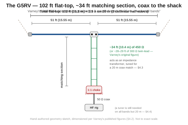
The matching section is not a BALUN and not a tuner — it is a fixed-length transmission-line transformer, doing exactly what any length of transmission line does to an impedance: rotating it around the Smith chart by an amount set by the line’s electrical length at the operating frequency. At 20 m, Varney’s 34-foot (or 28–29-foot) section is close to a half-wavelength on the ladder line’s own velocity factor, and a half-wavelength (or a multiple of it) of line repeats whatever impedance is at its far end, essentially unchanged, at its near end — so the matching section’s job on 20 m is to deliver the 2.5λ wire’s collinear-array impedance (a few tens to around a hundred ohms, comfortably reachable by a modest step or directly by coax with acceptable SWR) largely intact to the coax connection point. That is a deliberate, tuned-for-one-band transformation, not a general-purpose matching network — and outside 20 m, the same fixed length of line performs whatever transformation its different electrical length at that frequency happens to produce, with no guarantee it lands anywhere convenient.
3.4.3 The “all-band myth” — what the SWR profile actually shows
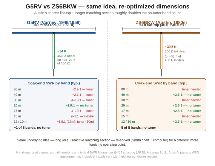
Because the antenna is genuinely a compromise centered on one band, its SWR profile at the coax end is the clearest evidence against the “all-band” marketing that has followed it for seventy years. Measured data (the numbers below are consistent with both the ARRL Antenna Book’s treatment and W8JI’s independently measured figures for a typical installation) show:
Table 2 — Because the antenna is genuinely a compromise centered on one band, its SWR profile at the coax end is the clearest evidence against the "all-band" marketing that has followed it for seventy years. Measured data (the numbers below are consistent with both the ARRL Antenna Book's treatment and W8JI's independently measured figures for a typical installation) show
| Band | Feedpoint-region impedance (approx.) | SWR on 50 Ω coax | Tuner needed? |
|---|---|---|---|
| 80 m | ~17 Ω, near-resistive | ~2.9:1 | Yes |
| 40 m | ~24 + j1 Ω | ~2.1:1 | Yes |
| 30 m | high, reactive | 6–10:1 | Yes |
| 20 m | ~90–96 Ω, near-resistive | ~1.9:1 | Marginal — the design band |
| 17 m | high, reactive | 4–6:1 | Yes |
| 15 m | ~22 Ω, near-resistive | ~2.3:1 | Maybe |
| 12 m | ~90–94 Ω, near-resistive | ~1.9:1 | Marginal |
| 10 m | reactive, feedline-loss-limited | 2.5–4:1 | Yes, and coax loss becomes the concern |
The honest read of that table is unambiguous: the G5RV delivers a genuinely usable (sub-2:1, or close to it) match on 20 m and, to a lesser and more installation-dependent degree, 12 m and 15 m, and needs a tuner everywhere else, sometimes badly — 30 m and 17 m in particular can present SWR in the 4–10:1 range, at which point coax loss (Section 3.3’s whole argument, applied here) starts eating a real fraction of the transmitted power even with a tuner cleaning up the rig-side match, because the tuner cannot undo the loss that already happened in the coax between the antenna and the shack. The G5RV is a 20 m antenna, with several other bands usable at various degrees of tuner-assisted compromise — an accurate description that has nothing to do with “all-band” as a marketing term implies. This is not a criticism of the design so much as a correction of seventy years of imprecise marketing copy; a well-built G5RV remains a genuinely fine 20 m antenna with useful bonus coverage elsewhere, which is exactly what Varney set out to build.
3.4.4 The ladder-to-coax junction and common-mode radiation
The point where the G5RV’s balanced ladder line meets unbalanced coax is architecturally awkward, and it is the second major source of real-world G5RV complaints (after the all-band myth). Connecting balanced line directly to coax — literally soldering the two conductors of the ladder line to the coax center and shield with no isolating device between them — is asymmetric by construction: coax has no equivalent of the ladder line’s “other conductor,” so one side of the balanced line ends up referenced to the coax shield and the other does not, and that asymmetry drives common-mode current onto the coax shield’s outer surface. That current does two unwelcome things: it makes the coax itself part of the radiating structure, in an uncontrolled and installation-dependent way that distorts the intended pattern and polarization, and it carries RF potential down the coax into the shack, showing up as RF-in-the-shack symptoms (chassis voltage, hot mic, desensitized receive) that have nothing to do with the antenna’s over-the-air performance.
The fix is the same device Vol 1’s OCFD discussion and Vol 2’s trap-dipole treatment both reach for: a 1:1 current choke (or, less commonly, a 4:1 current BALUN if an impedance step is also wanted) installed at the ladder-line-to-coax transition. A current choke does not fix the impedance match — the matching-section geometry of Section 4.2 does whatever it does regardless — but it does suppress the common-mode path, keeping the radiating structure closer to the intended flat-top-plus-matching-section and keeping RF off the coax shield heading into the shack. Whether to use a plain 1:1 choke or a 4:1 step is itself installation-dependent (a 4:1 step can help the SWR on some bands and hurt it on others, since it is transforming an already frequency-dependent impedance), and the amateur literature is genuinely split on the “right” answer — which is really a statement that there isn’t a single right answer independent of which bands you weight most heavily. What is not in dispute, despite persistent internet claims to the contrary, is that a properly installed matching section itself does not meaningfully radiate — the “the ladder line is secretly a vertical radiator” claim that circulates in some forum threads does not hold up against careful measurement and modeling, and the real common-mode story is entirely about the ladder-to-coax junction, not the balanced line itself.
3.5 ZS6BKW — Brian Austin’s re-optimization
3.5.1 History and design method
By the early 1980s, the G5RV’s popularity and its “all-band” reputation had outrun what the design actually delivered, and Brian Austin — at the time a South African radio amateur holding the callsign ZS6BKW (he later became active in the UK as G0GSF) — set out to see whether the same basic geometry (a horizontal flat-top plus a fixed balanced matching section feeding coax) could be re-optimized to genuinely match more bands without a tuner, rather than just one. Austin’s approach, described in his own published accounts and documented in the amateur antenna-modeling literature (notably L. B. Cebik’s detailed re-analysis of the G5RV family), combined early computer-based transmission-line and antenna modeling with manual Smith-chart work: rather than accepting Varney’s original 102 ft / ~34 ft pairing, Austin treated both the flat-top length and the matching-section length as free parameters and searched for a combination whose impedance, after transformation through the matching section, landed inside a tuner-free SWR window on as many HF bands simultaneously as the physics of a single wire and single fixed matching-line length would allow. His results were published in RSGB and South African amateur-radio literature in 1985 — Radio Communication (the RSGB journal, not renamed RadCom until 1995) and Radio ZS — with more formal treatments following in Elektron (1986) and the Journal of the IERE (1987), and the resulting antenna has carried his old callsign — ZS6BKW — as its name ever since.
3.5.2 Geometry: the 93-ft flat-top and the ~40-ft matching section
Austin’s optimized dimensions are a 93-foot flat-top (46.5 ft per leg) — noticeably shorter than the G5RV’s 102 ft — fed by a matching section of approximately 39.5 feet of 300 Ω twin-lead, or equivalently about 31 feet of 450 Ω ladder line if that’s the feeder stock on hand. Both the flat-top and the matching section moved from Varney’s numbers, and both moves matter: the shorter flat-top shifts every band’s electrical-length fraction relative to the G5RV, and the longer (in the 300 Ω case) or comparably-long (in the 450 Ω case) matching section changes the transformation the feeder applies at each of those shifted electrical lengths. The combination is a genuinely different point in the same design space Varney occupied, arrived at by deliberately searching that space rather than inheriting a pre-existing 1930s wire length.
3.5.3 SWR profile and the no-tuner band list
The payoff for Austin’s re-optimization shows up directly in the coax-end SWR profile. Where the G5RV manages a genuine sub-2.5:1, no-tuner match on essentially one band (20 m, with 12 m and 15 m as marginal bonus cases), the ZS6BKW’s re-solved geometry delivers SWR under roughly 2.5:1, without a tuner, on five of the eight traditional HF bands: 40, 20, 17, 12, and 10 metres — consistently reported across the modern ZS6BKW-vendor literature and cross-checked against independent NEC-modeling comparisons of the two antennas. The remaining three bands — 80, 30, and 15 metres — still require a tuner, and on 80 m in particular the ZS6BKW’s shorter flat-top (93 ft is a smaller fraction of a wavelength on 80 m than the G5RV’s 102 ft) means the antenna is electrically shorter there and the tuner has somewhat more work to do than it would feeding the longer G5RV wire on that band.
The engineering improvement is real and worth stating precisely: Austin roughly doubled the no-tuner band count relative to the antenna he started from, by treating the matching-section length as a genuine design variable to be solved for rather than a fixed historical accident, and by accepting a shorter, less “80 m comfortable” flat-top as the cost of spreading the good matches across more of the spectrum. That is not a claim that the ZS6BKW is unconditionally superior — Section 6 works through the actual trade — but it is a legitimate, well-documented instance of applying 1980s computational antenna analysis to improve on a design that had, by then, been essentially frozen by tradition for over two decades.
3.5.4 What changed, mechanically, and what it costs
The improvement is not free. A geometry solved for five simultaneous no-tuner bands is, by construction, more tightly constrained than one solved for a single band, and the amateur literature consistently notes that the ZS6BKW is more sensitive to installation details — height above ground, wire sag, proximity to nearby structures, and end-effect from insulators and hardware — than the G5RV, precisely because its dimensions were tuned to hit five separate targets rather than optimized loosely around one. A ZS6BKW built a few inches off in either wire (flat-top or matching section) will drift further from its five-band no-tuner performance than a G5RV built with the same tolerance drifts from its one-band target, simply because there are more constraints to satisfy simultaneously and less margin at each one. The build-and-tune discipline this demands — cut to the published dimensions carefully, verify with an analyzer rather than assuming the published numbers transfer perfectly to your installation, and be prepared to trim in small increments while re-checking multiple bands rather than just the one you’re chasing — is the price of the wider no-tuner coverage, and it is why the amateur consensus (echoed in Cebik’s detailed re-analysis) treats the ZS6BKW as the antenna for the operator willing to trim carefully, and the G5RV as the antenna for the operator who wants seventy years of forgiving, well-trodden community experience behind a known-good, less fussy build.
3.6 G5RV vs ZS6BKW — head-to-head
Putting Sections 4 and 5 side by side:
Table 3 — Putting Sections 4 and 5 side by side
| Factor | G5RV | ZS6BKW |
|---|---|---|
| Flat-top | 102 ft (51 + 51) | 93 ft (46.5 + 46.5) |
| Matching section | ~34 ft of 450 Ω (or ~28–29 ft of 300 Ω) | ~39.5 ft of 300 Ω (or ~31 ft of 450 Ω) |
| Genuine no-tuner bands | ~1 (20 m); 12/15 m marginal | ~5 (40, 20, 17, 12, 10 m) |
| Bands still needing a tuner | 80, 40, 30, 17, (15) | 80, 30, 15 |
| Design intent | Optimized for 20 m specifically | Optimized for the broadest simultaneous no-tuner spread |
| Installation sensitivity | Lower — decades of forgiving community experience | Higher — tighter multi-constraint solution, trim carefully |
| History / community depth | ~80 years, the most-built compromise wire antenna in amateur radio | ~40 years, a smaller but technically well-documented following |
| 80 m performance | Comparatively better (longer flat-top) | Comparatively worse (shorter flat-top, more tuner-dependent) |
Neither design is strictly better; they optimize for different things. The G5RV is the right choice for an operator whose primary HF interest actually is 20 m, who wants the deepest well of community build experience and troubleshooting knowledge to draw on, and who is comfortable reaching for the tuner on every other band without expecting much beyond “the tuner can find a match, more or less.” The ZS6BKW is the right choice for an operator who wants to run largely tuner-free across the high-traffic HF bands (40 through 10 m, missing only 30 and 15 m from that list) and is willing to accept a fussier build and a materially worse 80 m story as the cost of that spread.
3.7 Choosing among the three
Stepping back to the full trio this volume covers, the decision reduces to how much you want the antenna’s fixed geometry to do versus how much you’re willing to leave entirely to the tuner:
- Want the highest achievable efficiency across every HF band, already own (or are willing to buy) a genuine balanced tuner, and don’t mind that every band-change means the tuner re-solves the match from scratch? Build a doublet (Section 3). It is the purist’s answer: no traps, no compromise BALUN ratio, no off-center asymmetry — just a wire, ladder line, and a tuner doing honest work every time.
- Primarily a 20 m operator who wants the best-documented, most forgiving multi-band compromise wire in amateur radio, with occasional bonus bands at various tuner-assisted qualities? Build a G5RV (Section 4). Seventy-plus years of community experience means every failure mode is well understood and every fix is well documented.
- Want to operate largely tuner-free across 40 through 10 m specifically, are comfortable with a more exacting build, and can accept that 80 m becomes a fully tuner-dependent band? Build a ZS6BKW (Section 5). It is the more sophisticated engineering answer to “how few bands can I leave to the tuner,” at the cost of a fussier install.
All three assume the operator already has, or is willing to acquire, a balanced tuner or an unbalanced tuner plus a suitably-rated current BALUN (Section 3.4) and a run of balanced ladder line into the shack through a proper feed-through panel — none of these designs is a drop-in replacement for a coax-fed OCFD or fan dipole for an operator unwilling to deal with balanced feedline. The commercial-buy survey for balanced tuners and ladder-line hardware, alongside the rest of the multi-band family’s DIY build and buy guidance, is in Vol 5.
3.8 Common gotchas and myths
- “The G5RV is an all-band antenna” — the most persistent myth in the wire-antenna hobby. Varney designed a 20 m antenna; the coverage on other bands is a byproduct of the 102 ft wire’s harmonic behavior, ranges from marginal to poor depending on band, and requires a tuner on most of the HF spectrum. “Multi-band, tuner-assisted, genuinely good on one band” is the accurate description.
- “The ladder line/matching section radiates a vertical component” — a durable internet claim, and one that careful modeling and measurement do not support for a properly built and routed matching section. The real common-mode story on a G5RV or doublet is the ladder-to-coax junction, addressed with a current choke (Section 4.4), not the balanced line itself doing anything mysterious.
- “Any length works for a doublet” — mostly true, and it’s a real strength of the design, but not unconditionally: a length that lands the antenna on an integer number of wavelengths on a band you use puts a current node (high, sharply reactive impedance) right at the feed, which combined with an unlucky matching-line length can push the match outside even a good tuner’s range (Section 3.2). Check the geometry, or at least be prepared to find the one band where the tuner struggles.
- “Higher characteristic impedance is why ladder line loses less” — the impedance number is incidental. The advantage is low conductor resistance and minimal dielectric in the loss path, which happens to correlate with the wide-spaced, high-Z designs sold as ladder line, but the mechanism is conductor-versus-dielectric loss, not the ohms figure on the spec sheet (Section 3.3).
- “The ZS6BKW is a strict upgrade over the G5RV” — it wins on no-tuner band count and loses on installation forgiveness and 80 m performance. Which one is “better” depends entirely on which bands you actually operate and how much trimming patience you have (Section 6).
- “A balanced tuner isn’t necessary if my unbalanced tuner shows a good SWR” — an unbalanced tuner fed through a plain 4:1 BALUN can find a numerically low SWR at the coax input while still carrying real common-mode current on the ladder line if the BALUN’s ratio is off at that particular frequency and impedance. A good SWR reading at the rig does not, by itself, prove the feedline is behaving as a clean balanced transmission line.
3.9 Where this volume hands off
This volume took the “high-impedance feed” and “compromise-length” rows of Vol 1’s multi-band decision table and developed them to full engineering depth. The doublet (Section 3) is the purist’s tuner-fed design: a non-resonant flat-top of carefully-chosen length, fed with low-loss balanced ladder line into a balanced tuner (or a 4:1 current BALUN plus an unbalanced tuner as the simpler, slightly lossier alternative), delivering genuinely all-band coverage at the cost of a multi-lobed, band-dependent pattern on the higher HF bands and full reliance on the tuner every time the band changes. The G5RV (Section 4) is Varney’s 102-foot, ~34-foot-matching-section compromise, designed for and genuinely good on 20 m, usable elsewhere with a tuner and highly variable results, and burdened with seventy years of “all-band” marketing that the SWR data in Section 4.3 does not support. ZS6BKW (Section 5) is Brian Austin’s deliberate re-optimization of the same basic geometry — a shorter 93-foot flat-top and a longer ~39.5-foot matching section — that roughly doubles the genuinely no-tuner band count to five, at the cost of a fussier build and a weaker 80 m story.
Vol 4 picks up the two remaining rows from Vol 1’s table — the linked dipole (mechanical band-switching by inserting or removing jumpers, the SOTA/POTA favorite) and the cage dipole (the single-band-but-multi-band-adjacent wide-bandwidth specialty) — and closes out the family-wide best-case/worst-case matrix and power-handling comparison that spans every design in Vol 1 through Vol 4. Vol 5 carries the hands-on DIY build (a Buckmaster-style OCFD, the highest-utility-per-dollar build in the family) and the commercial-buy survey, including the balanced tuners and ladder-line hardware every design in this volume depends on.
3.10 Resources
- ARRL Antenna Book (25th+ ed.), the multi-band-antenna and transmission-line chapters — the canonical reference for G5RV dimensions, the doublet-length guidance, and the ladder-line-versus-coax loss-under-SWR data used throughout this volume.
- Louis Varney, G5RV, original design articles, RSGB Bulletin / Radio Communication (1946 onward, definitive form 1958) — the foundational G5RV publication.
- Brian Austin, ZS6BKW (later G0GSF) — the ZS6BKW re-optimization of the G5RV geometry, published in Radio Communication (RSGB), August 1985, and Radio ZS, June 1985, with more formal treatments in Elektron (1986) and the Journal of the IERE (1987). The derivation and its computer/Smith-chart optimization method are analyzed in depth in L. B. Cebik’s “The G5RV Antenna System Re-Visited.”
- L. B. Cebik (W4RNL), “The G5RV Antenna System Re-Visited” (multi-part) — the deepest amateur-literature re-analysis of the G5RV and ZS6BKW family, including NEC-modeled pattern and impedance comparisons; archived across the antenna-modeling community.
- W8JI (Tom Rauch), G5RV technical notes — an independently measured, skeptical technical treatment of G5RV impedance and SWR data by band, useful as a cross-check against the manufacturer and historical literature.
- Sevick, Transmission Line Transformers (5th ed.) — the BALUN/UNUN design reference for the 4:1 current BALUN option at the ladder-to-coax junction.
- Walter Maxwell, W2DU, Reflections (3rd ed.) — the standing-wave/impedance/feedline-loss bible that underlies the ladder-line-under-high-SWR argument in Section 3.3.
Comments (0)