Multi-Band Dipoles · Volume 4
Linked & Cage Dipoles, and Choosing Across the Family
The linked dipole's per-band resonance bought back by physically relinking the wire — link hardware, the cut-from-center-out workflow, and why it's the SOTA/POTA default; the cage dipole's diameter-driven bandwidth widening (a single-band technique, not a multi-band one); a decision guide across OCFD, fan, trap, doublet, G5RV/ZS6BKW, linked and cage; and power handling across the whole family
4.1 About this volume
Vol 1 §3 named four structurally distinct families for putting more than one band on a single length of wire — harmonic/off-center feed, parallel or trapped resonators, tuner-fed nonresonant designs, and switched/linked designs — and worked the first of those, the off-center-fed dipole and its Carolina Windom cousin, in full. Vol 2 took the second family, the fan dipole and the trap dipole, both of which keep the feedpoint centered and instead multiply or gate the resonant structure itself. Vol 3 took the third, the doublet, G5RV, and ZS6BKW, which hand the entire matching problem to a tuner fed through low-loss balanced ladder line rather than trying to present 50 Ω to coax at all. Every one of those designs, underneath its particular trade, is answering the same question: how do you get more than one band out of a wire you only have room to hang once?
This closing volume takes the fourth family — switched/linked designs — and adds the one variant that does not fit any of the four because it is not answering the multi-band question in the first place: the cage dipole. The linked dipole does not compromise resonance at all; it is a full-size, single-band half-wave dipole for whatever band it is currently configured for, and it gets there by making the wire’s electrical length a physically adjustable thing — open or close a handful of connectors, and the same wire becomes a different, fully resonant antenna. The price is operational rather than electrical: you have to lower the antenna to change bands, which is precisely why this design lives and dies by use case rather than by antenna theory, and precisely why it has become the de facto standard for SOTA and POTA portable operation. The cage dipole, riding along in this volume for reasons of tradition and adjacency rather than kinship with the other six designs, is not a multi-band antenna at all; it is the wide-bandwidth answer to a single-band problem — making one band’s worth of full-size dipole cover the entire band at an acceptable SWR without a tuner — and it earns its place here specifically as the thing a multi-band-minded builder reaches for instead of a doublet or an OCFD when what is actually wanted is generous coverage of one wide, low band. Both designs get the same treatment Vols 1–3 gave their subjects: how they work, what real hardware exists, and where each wins or loses against its siblings.
With every variant across the four families now on the table, Section 4 does the job Vol 1 §3 could only gesture at — a genuine decision guide that sorts the whole family (OCFD, fan, trap, doublet, G5RV/ZS6BKW, linked, cage) by the constraint that actually binds a given station: resonant-and-lossless, tuner-and-flexible, harmonic-and-simple, or shortened-and-lossy, cross-cut by use case (home multiband, portable/SOTA, restricted space, contest). Section 5 then closes the loop on power handling across the entire family — trap voltage and heat limits, OCFD BALUN heating, ladder line’s forgiving behavior under high SWR versus coax’s unforgiving one, and the reason a linked or fan dipole is the simplest full-legal-limit multi-band answer of the whole lineup. Vol 5 carries the hands-on DIY build and the commercial-buy survey for the family as a whole.
4.2 Linked dipole — resonant-per-band by physical relinking
4.2.1 The concept, and why it is the low-loss choice
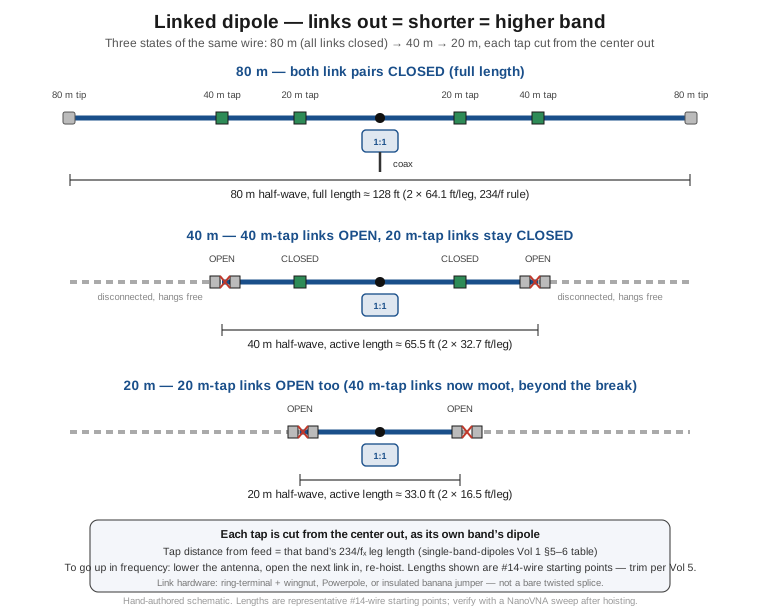
A linked dipole is, at any given moment, nothing more exotic than a single-band half-wave dipole — the canonical reference antenna the single-band-dipoles dive builds from first principles. What makes it a multi-band antenna is that its physical length is adjustable in the field: the wire is built long enough for the lowest band you want, and at the point along each leg where a higher band’s resonant length is reached, a small removable connector — the link — sits in the wire. Close every link and the full length is in circuit, resonant on the lowest band. Open the links beyond a higher band’s resonant point and the antenna is now physically shorter, resonant on that higher band, with the excess wire beyond the open link hanging disconnected and electrically irrelevant.
This is a fundamentally different trade than anything in Vols 1–3 make. The OCFD, fan, trap, and doublet/G5RV family all multi-band a fixed piece of wire — the antenna’s physical geometry never changes, and the multi-band trick lives entirely in feedpoint placement, parallel resonators, reactive traps, or a tuner absorbing whatever impedance the wire presents. A linked dipole instead keeps the electrical problem as simple as it can possibly be — cut the right length, feed it in the center, done — and moves the multi-band problem into the mechanical domain. The payoff is that every band the linked dipole is configured for is a full-size, fully resonant half-wave dipole, with the same ~73 Ω free-space feedpoint, the same near-unity radiation efficiency, and the same clean 1:1-current-BALUN feed as the single-band reference antenna (Single-Band Dipoles Vol 1–2) — no trap loss, no off-resonance reactance for a tuner to fight, no compromise BALUN carrying multi-band stress across a 10:1 frequency span. The cost is that changing bands means physically reaching the links, which for a fixed installation strung between two supports at height is a genuine nuisance (lower the whole antenna, work at each connector, re-hoist, re-tension) — and it is exactly this cost/benefit split that explains the linked dipole’s real-world niche almost completely on its own. Where a station’s bands are fixed for the operating session and the antenna doesn’t need to move — a SOTA or POTA activation working one or two bands from a single stop, a Field Day station with its antenna up for a fixed duration, a portable QRP setup deployed once per outing — the “lower it to change bands” cost is paid once or twice a session and the full per-band efficiency is pure upside. Where bands need to change minute to minute at a fixed home station, it is the wrong tool, and a fan dipole (Vol 2) or an OCFD (Vol 1) — the resonant-per-band and harmonic-per-band answers — is the right one instead.
4.2.2 Link hardware
The link itself is the one piece of hardware this design lives or dies by in the field, and the amateur community has settled on a handful of approaches that trade reliability against speed:
Ring terminals with a wingnut or bolt are the most field-serviceable option and the one SOTABeams and most DIY builds default to: each side of the break terminates in a crimped ring terminal, and closing the link means threading a stainless bolt or wingnut through both rings and tightening. It is slow to change (each link is a proper mechanical/electrical joint, not a snap connection) but essentially immune to the wet-weather intermittent-contact problem that plagues faster connectors, and it tolerates being handled with cold, gloved fingers on a windy summit — a real consideration for the SOTA crowd this design serves.
Insulated banana-plug jumpers (a Pomona-style test-clip lead with a 4 mm or 5 mm banana plug on one end mating into a jack on the wire) are the fast option: pull the jumper to open the link, plug it back in to close it, no tools required. The tradeoff is exactly what you would expect from a spring-contact connector exposed to weather — a jumper that has spent a season getting rained on develops higher, less repeatable contact resistance than a bolted ring joint, and for high-power operation the smaller contact area is a real (if usually secondary) concern next to the wire-heating limits discussed in Section 5.
Powerpole-style connectors, borrowed from the DC-power side of the hobby, split the difference — a positive mechanical latch, weather resistance considerably better than a bare banana jack, and a fast one-handed disconnect — and have become a popular third option particularly among builders who already keep a stock of Powerpole housings and crimp tooling on the bench for 12 V gear.
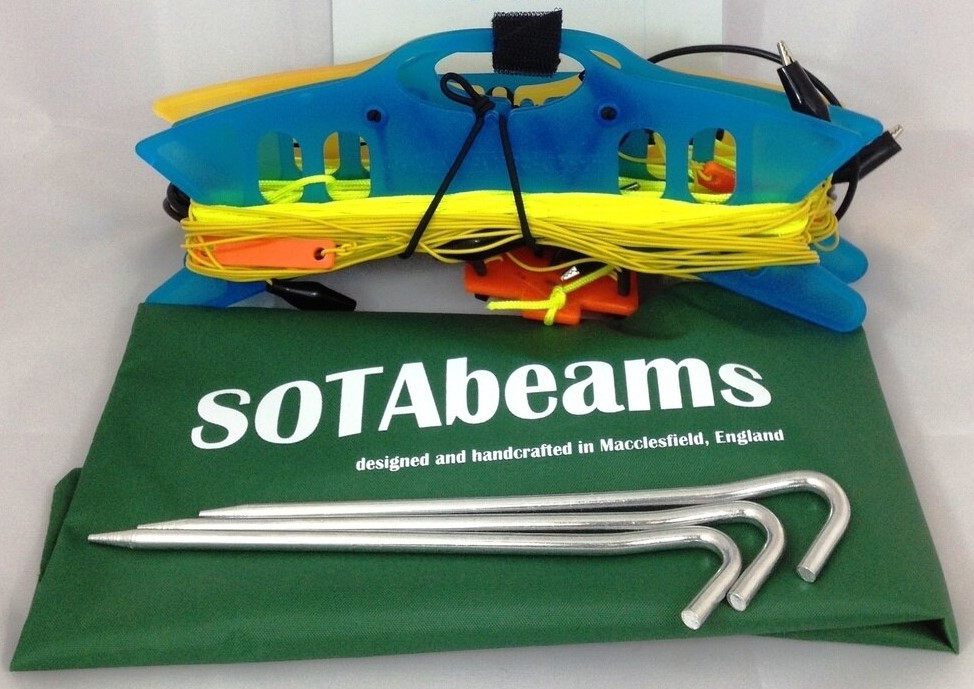
Alligator clips, the fastest and cheapest option of all, are what SOTABeams’ own Band Hopper series actually ships with — the vendor’s own product literature describes changing bands as “opening or closing the two breaks on each side with alligator clips.” They are the right choice for a design whose entire premise is minimizing weight and setup time on a summit, and the tradeoff — a spring-jaw contact is the least weatherproof and lowest-current of the options here — is one the SOTA community has evidently decided is an acceptable price for speed and the few-hundred-milliwatt-to-low-tens-of-watts power levels most portable QRP-to-100 W operation runs at. What none of these is, in any serious build, is a bare twisted-and-taped splice — a joint that depends on tape for both its mechanical integrity and its weather sealing is the one link style that reliably degrades over a season of field use, and every commercial and community-documented DIY design uses one of the four connector styles above instead.
4.2.3 Cutting each band’s length from the center out — the band-change workflow
The build procedure follows directly from treating the linked dipole as several single-band dipoles that happen to share a feedpoint and a spool of wire. Start from the lowest band you want (the longest leg) and work outward is the wrong mental model — the correct one, and the one the reference designs actually use, is to build from the center out: cut the wire long enough for the lowest band, install the feedpoint and a 1:1 current BALUN exactly as a single-band dipole would (Single-Band Dipoles Vol 2), then measure outward from the feedpoint to each higher band’s own resonant leg length — the same 234/f_MHz per-leg starting point the single-band-dipoles dive tabulates — and install a link at that point on each leg. The wire beyond the highest-band link, out to the tip, is simply the remainder needed to reach the lowest band’s full length once every link is closed.
This is why the figure above shows three concentric states rather than one: closing every link gives the full-length, lowest-band antenna; opening the outermost link pair disconnects the tip segments and leaves an active length equal to the next band up; opening the next pair in shortens it again. Each opened link’s downstream wire does not need to be removed — it simply hangs disconnected from the working antenna, which is why field practice is to physically separate the open link (rather than merely loosen it) so the dangling segment cannot swing back into accidental contact with the closed portion in wind. The per-band tap lengths are, like any dipole cut length, starting points for #14-class wire that want confirming with a NanoVNA sweep after hoisting — the same cut-long-hoist-sweep-trim discipline Single-Band Dipoles Vol 5 documents applies per band here, with the added wrinkle that trimming one band’s tap can very slightly shift the electrical length seen by the bands beyond it (the same multi-wire-interaction effect Vol 2’s fan dipole shows, though generally milder here because only one length is in circuit at a time rather than several parallel resonators simultaneously present).
The operational band-change sequence this geometry drives is short and mechanical rather than electrical: lower the antenna (or, for an inverted-V-style single-mast linked dipole, simply reach the apex and let the legs down), open or close the appropriate link pair, re-hoist, and re-tension. For a well-practiced SOTA operator this is routinely a five-minute affair including a quick SWR check; it is also, unambiguously, the operation a fixed multi-band home station with several stations and operators wanting instant band changes cannot tolerate — which is the entire reason Vol 1’s OCFD and Vol 3’s doublet exist for that use case instead.
4.2.4 The SOTA/POTA reference design and a DIY build
SOTABeams’ Band Hopper series (Macclesfield, UK) is the closest thing the SOTA/POTA community has to a de facto standard linked dipole, and it is worth treating as the reference design because its published specifications are representative of the whole genre. The Band Hopper III covers 20/30/40 m as a genuinely full-size half-wave dipole on each band, using alligator-clip links at the breaks on each leg; the Band Hopper IV extends the same approach to add 80 m. Both ship as an extremely light package — SOTABeams’ own figures put the complete Band Hopper III system (antenna, wire winders, feeder, and back guy) at well under 500 g — built from a 10 m run of RG-174 coax preterminated with a BNC connector as the feeder, with a second 10 m length doubling as a back-guy for the supporting mast. The vendor does not publish the exact per-band tap distances as a separate spec sheet figure; the practical implication for a builder duplicating or repairing one is to use the same 234/f_MHz-per-leg starting point Single-Band Dipoles Vol 1 §5–6 tabulates for each band, verified on a NanoVNA once hoisted, exactly as Section 2.3 describes.
A DIY linked dipole built from scratch, rather than bought, is one of the cheaper multi-band antennas in this entire dive to assemble, precisely because it needs none of the exotic parts — no traps, no 4:1 or 9:1 transformer, no ladder line — that the other variants require. A representative 40/30/20 m build, sized for portable rather than fixed-station duty:
Table 1 — A DIY linked dipole built from scratch, rather than bought, is one of the cheaper multi-band antennas in this entire dive to assemble, precisely because it needs none of the exotic parts — no traps, no 4:1 or 9:1 transformer, no ladder line — that the other variants require. A representative 40/30/20 m build, sized for portable rather than fixed-station duty
| Part | Specification | Role |
|---|---|---|
| Stranded copper antenna wire, #18–#20 | Lightweight (portable) or #14 (fixed-install durability) | The radiating element, cut long for 40 m |
| Ring-terminal + wingnut, or Powerpole, link pairs | 4 total (2 per leg, one per higher-band tap) | The band-change points |
| Lightweight center insulator + 1:1 current BALUN | Small toroid (Mix 43 for portable weight, Mix 31 for fixed-install power) | Feedpoint, exactly as a single-band dipole (Single-Band Dipoles Vol 2) |
| End insulators | Ceramic (fixed) or lightweight polymer (portable) | Standard dipole-end hardware |
| Feedline | RG-174 or similar light coax (portable) / RG-8X or better (fixed, higher power) | Matched to the duty cycle and power level |
| Halyard / guy rope | Dacron, sized to the mast | Support |
The build sequence is the same center-out procedure Section 2.3 describes: cut the 40 m length first, install the feedpoint and BALUN, sweep and trim the full-length antenna to 40 m resonance, then measure out to the 30 m and 20 m tap points, install the links, close them all, and confirm each band’s resonance in turn as the links are opened progressively — the same cut-long-hoist-sweep-trim NanoVNA discipline Single-Band Dipoles Vol 5 develops in full applies unchanged, run once per band rather than once total.
4.3 Cage dipole — wide bandwidth on one band, not a multi-band answer
4.3.1 Geometry and construction
The cage dipole is included in this dive for reasons of tradition and adjacency, not electrical kinship with anything else in this volume, and the point is worth stating plainly before the description of how it works: a cage dipole is not a multi-band antenna. It is a single-band half-wave dipole — the same canonical reference geometry as any dipole in the single-band-dipoles dive, cut to the same 468/f_MHz starting length — built from multiple parallel conductors instead of one, tied together at the center feedpoint and at each end, held at constant spacing by insulating spreaders along the element’s length. The reason it belongs in a survey of “solutions to the multi-band wire-antenna problem” at all is that it answers a closely adjacent question a multi-band builder often actually has: I only care about one band, but I want the whole band, at an acceptable SWR, without a tuner — and for a wide low band like 80 m or 160 m, a plain single-wire dipole cannot deliver that on its own.
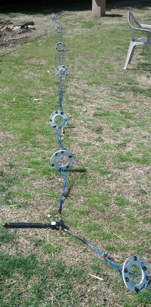
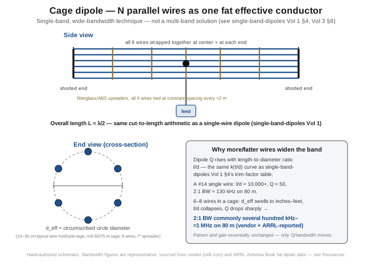
A representative build, drawn from a currently available commercial example, uses six parallel wires per leg, held at constant spacing by a 7-inch-diameter round spreader (a common material choice is 1/4-inch ABS plastic disks), shorted together at the tip of each leg and strapped together at the center feedpoint exactly as a single conductor’s tip and center would be. The overall length is unchanged from the equivalent single-wire half-wave dipole’s 468/f_MHz (a representative 80/75 m cage dipole comes out to roughly 125 ft, essentially the same figure Single-Band Dipoles Vol 1 §6’s length table gives for one wire on that band) — the cage construction changes the element’s effective diameter, not its resonant length.
4.3.2 The Q-and-bandwidth physics, tied to the single-band reference
The mechanism is the same one Single-Band Dipoles Vol 1 §4 develops for why a fatter single conductor trims shorter and behaves differently near resonance: a dipole’s Q, and therefore its 2:1-SWR bandwidth, is set by its length-to-diameter ratio — the same ℓ/d figure that volume’s trim-factor table already tabulates from the thin-#18-wire end (ℓ/d in the tens of thousands, k ≈ 0.96, high Q, narrow band) down through fat VHF tubing (ℓ/d in the low hundreds, k ≈ 0.92, lower Q, wider band) — the same relationship Single-Band Dipoles Vol 3 §8 plots directly as a fat-element/cage curve against a thin-wire SWR sweep. A cage of several parallel wires is, from the antenna’s perspective, one much fatter effective conductor — the current on resonance divides across the parallel wires roughly as it would across a single solid conductor of the cage’s circumscribed diameter, and that effective diameter routinely runs to inches on a hobbyist build and can be built out to several feet on a dedicated wideband installation. Collapsing ℓ/d this aggressively drives Q down sharply, and bandwidth (which scales inversely with Q for a fixed resonant frequency) opens up correspondingly: where a single #14 wire dipole on 80 m covers on the order of 130 kHz at 2:1 SWR — a little over a quarter of the band — a cage of several wires with an effective diameter in the several-inches-to-a-foot range is commonly reported, across both vendor literature and the ARRL Antenna Book’s fat-dipole treatment, in the range of several hundred kHz to close to a megahertz at 2:1–3:1 SWR, comfortably spanning the entire 80/75 m band including both the CW and phone segments. The radiation pattern and gain are essentially unaffected by any of this — the wider bandwidth is bought entirely from the reactance-versus-frequency slope near resonance, exactly as it is for the fat-tubing VHF case, not from any change to the antenna’s radiating geometry.
It is worth being precise about what widening the bandwidth this way is not doing, because the intuitive-sounding shortcut — “just use heavier gauge wire” — does not work. Moving from thin wire to, say, #12 solid copper changes the ohmic loss resistance negligibly (a full-size HF dipole’s radiation resistance already dwarfs its wire resistance, as Single-Band Dipoles Vol 5’s power-handling treatment establishes) and barely moves ℓ/d at all, because a factor-of-two change in wire diameter is a rounding error against a length-to-diameter ratio already in the thousands. What actually moves Q is a change in effective diameter measured in inches or feet, and the only practical way to get there on a wire antenna — short of building from solid metal tubing, which is a mechanical and cost non-starter at 80 m or 160 m lengths — is the cage’s trick of using several separated conductors to synthesize a large effective diameter from ordinary wire.
4.3.3 Where it earns its keep — and where it does not
The cage dipole’s case is narrow but genuine: it is worth the mechanical complexity specifically on the wide, low HF bands — 80 m at 500 kHz wide and 160 m wider still — where a single-wire dipole’s native bandwidth, even well-trimmed, leaves most of the band outside a comfortable 2:1 SWR window and a tuner (or an accepted higher SWR near the band edges) is otherwise mandatory. It is close to pointless on any band narrow enough that a plain thin-wire dipole already covers the whole thing at 2:1 without help — 40 m and up are, in ordinary #14 wire, already inside their own native bandwidth across the entire allocation, and building a cage there buys nothing worth its mechanical cost. The mechanical cost is real and should not be understated: a full 80 m cage needs a spreader every couple of meters along its full length to keep several parallel wires from twisting together, each spreader is a wind-loaded structure in its own right, and a builder should budget for meaningfully more wind and ice load than an equivalent single-wire dipole — ARRL’s own station W1AW has operated an 80 m cage dipole (documented in an ARRL technical note describing the installation), which is a fair data point that the approach is a legitimate, if unusual, choice even for a well-resourced station rather than a fringe curiosity, but it is unambiguously a bigger build project than stringing a single wire.
The honest comparison this dive owes the cage dipole is against its closest multi-band-family relative in spirit: a doublet fed with ladder line into a tuner (Vol 3) also delivers “the whole band, low loss” on 80 m, and does so with genuine multi-band coverage of every other HF band as a bonus, at the cost of needing a tuner and accepting a balanced-line feed into the shack. The cage dipole’s case over the doublet is narrow and specific: no tuner, ever, on this one band — a real advantage for an operator who lives on 80 m and wants to spin the VFO across the whole band without touching a match, but not a reason to build one if the doublet’s tuner-and-ladder-line answer is already acceptable and multi-band coverage on the other bands is also wanted.
4.4 Choosing across the family — a decision guide
With every variant now on the table — OCFD (Vol 1), fan and trap (Vol 2), doublet and G5RV/ZS6BKW (Vol 3), and this volume’s linked and cage dipoles — the family sorts cleanly into four trade postures, plus the cage dipole’s single-band special case sitting alongside them.
Resonant and lossless — the fan dipole and the linked dipole both deliver a genuinely resonant, near-zero-compromise feedpoint on every band they cover, because both are, electrically, just single-band dipoles wired (or reconfigured) in parallel or in series with themselves. The fan dipole pays for this in mechanical fuss during the build (the multi-iteration trim-and-resweep cycle Vol 2 documents, since the parallel wires interact) and in the wind-loaded complexity of several wires sharing a feedpoint; the linked dipole pays for it operationally, in the time it takes to lower the antenna and relink for a different band. Neither burns power in a trap or a compromise BALUN, and both are the right default whenever “no tuner, no loss, full per-band performance” is the actual requirement.
Harmonic and simple — the OCFD (and its Carolina Windom cousin) occupies this category alone: a single wire, a feedpoint moved off-center (conventionally near the 1/3 point) to find harmonic impedances that cluster near a workable ratio, and a 4:1 current or 6:1 voltage BALUN carrying the resulting multi-band stress. It is the “plug the coax in and operate” answer for four to eight bands on one feedline depending on the exact geometry and vendor, at the cost of pattern asymmetry and harmonic-band lobe fragmentation (a real consideration for anyone chasing consistent coverage in every direction) and a BALUN that runs harder across a wider frequency span than any single-band feedpoint choke has to.
Tuner and flexible — the doublet and the G5RV/ZS6BKW family both hand the entire multi-band matching problem to a tuner at the shack end, fed through low-loss balanced ladder line rather than coax. The doublet is the purist’s answer: genuinely all-band, highest efficiency of anything in this survey, at the cost of needing a balanced tuner and a way to route ladder line into the shack. The G5RV (102 ft flat-top, ~34 ft matching section) and its ZS6BKW refinement (a shorter 93 ft flat-top, ~39.5 ft matching section) fix a specific wire-plus-ladder-line combination — good, well-documented, no-surprises designs, but ones that are honestly a 20 m antenna usable elsewhere with a tuner (G5RV) or a deliberately engineered five-no-tuner-band compromise (ZS6BKW, at the cost of a fussier build and a weaker 80 m story) rather than a genuinely flat all-band performer.
Shortened and lossy — the trap dipole is the family’s one entry that explicitly trades efficiency for length: LC traps let a physically short wire cover multiple bands, at the cost of real per-trap power dissipation (a fraction of a dB to a couple of dB depending on how many traps a given band’s signal passes through) and narrowed per-band bandwidth. It earns its keep exactly once — when the antenna genuinely will not fit at fan-dipole or OCFD length and the lot size is the hard constraint — and is a worse choice than either of those alternatives whenever the real estate exists to avoid it.
Single-band wideband (not multi-band at all) — the cage dipole stands outside the four postures above because it is not solving the multi-band problem in the first place; it is the answer to “cover all of one wide band without a tuner,” and belongs in this survey only because that question so often arises for the same builder weighing a multi-band doublet or OCFD against simply not multi-banding at all.
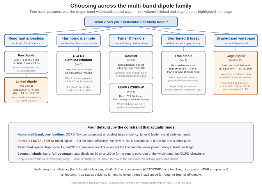
Cross-cut by use case rather than by trade posture, the same family resolves into four practical defaults. For home multiband operation with a single feedline and no particular tolerance for mechanical fuss, the OCFD is the standard modern answer, with the doublet as the higher-efficiency alternative for anyone who already owns a balanced tuner and can route ladder line into the shack. For portable, SOTA, or POTA operation, the linked dipole is close to the uncontested default in that community for exactly the reason Section 2 develops — full per-band efficiency, at an operational cost (lower-relink-rehoist) that a single-operator, single-location activation pays easily. For restricted space, where the antenna genuinely cannot reach fan-dipole or OCFD length, the trap dipole remains the compact-footprint answer, with the explicit understanding that it is trading efficiency and (Section 5) some power headroom for the shorter wire. For contest or single-band-focused operation, particularly on the wide low bands, the cage dipole’s full-band no-retune coverage on 80 m or 160 m is worth its mechanical cost specifically because a contest operator moving across the whole band under time pressure has no patience for a tuner or a narrow native bandwidth, while a fan dipole or OCFD remains the right choice for whichever other bands that same contest operation needs to cover simultaneously.
4.5 Power handling across the family
Every multi-band dipole in this dive shares the three baseline power-handling limits Single-Band Dipoles Vol 5 §2 develops for the canonical half-wave element — wire ampacity (almost never the binding limit for anything #14 or heavier), end-insulator dielectric strength and creepage (a genuine concern at the several-kilovolt tip voltages a legal-limit dipole develops), and feedpoint-choke core heating. What changes, variant to variant, is which additional component the multi-band trick itself introduces as a new, often lower, ceiling.
Trap voltage and heat are the trap dipole’s hard limit, and the physics is worth being specific about because it explains why trap dipoles are the one variant in this family that does not scale comfortably to amplifier power. A trap’s capacitor sees a voltage that rises with both the RF power passing through it and the trap’s own reactive impedance at the operating frequency; at a modest 100 W into a well-matched trap, a back-of-envelope V ≈ √(P·Q·X₀) from Vol 2’s own worked trap example (X₀ ≈ 250 Ω, Q ≈ 134–465) puts the capacitor voltage in the neighborhood of 1.5–3.5 kV — meaning even a nominally “2 kV” capacitor can be running close to its rating, and anything rated 1 kV or below will arc and fail at that power level. Scaling to a full 1.5 kW legal-limit amplifier multiplies that voltage stress roughly with the square root of the power ratio, which is why the ARRL Antenna Book and the trap-building literature both call for vacuum-variable capacitors or high-voltage doorknob/transmitting-mica capacitors rated in the 5 kV-and-up range for anything approaching legal limit — the light-duty capacitors that suffice in a 100 W trap dipole are simply the wrong part for an amplifier station. The failure mode this produces in the field is distinctive and worth recognizing: a trap that is being overdriven arcs internally, often audibly (an operator running a trap dipole hard sometimes reports hearing a faint “tick” or “ping” through a nearby receiver at the moment of failure), and the symptom that follows is the SWR on that trap’s design band jumping toward infinity as the now-open trap stops passing current at all.
BALUN heating is the OCFD’s binding limit, exactly as Vol 1 §9 develops in detail: the feedpoint BALUN has to maintain its impedance ratio and its choking performance across a full 8- to 10:1 frequency span while carrying every watt the station transmits on every band — a materially harder duty cycle than a single-band dipole’s 1:1 choke ever sees, and one made worse by the fact (also Vol 1’s) that the BALUN’s nominal 4:1 or 6:1 ratio is itself only approximate, drifting by as much as ±25% across that span. Commercial OCFD baluns are sold in two tiers rather than a single legal-limit rating — roughly a 300 W unit for the 100-watt-class transceiver and a 3 kW “HP” unit on larger toroids for amplifier/legal-limit use (Vol 1 §9) — and even the HP unit should not be asked to carry full power for extended periods on a band where the antenna’s actual feedpoint impedance departs furthest from the balun’s design center, since that mismatch reflects power back into the core rather than out onto the wire. The comparative point worth adding here: this is a strictly harder problem than the single-band choke Single-Band Dipoles Vol 5 §2 treats, precisely because the OCFD’s BALUN never gets to relax into a single, well-matched design frequency the way a plain dipole’s choke does.
Ladder line’s forgiving behavior under high SWR is the doublet’s structural power-handling advantage, developed in full in Vol 3 §3.3: because ladder line’s loss is dominated by conductor resistance rather than the dielectric dissipation that governs coax, its loss barely changes across a wide SWR range — commonly reported as roughly an order of magnitude below a comparable coax’s loss at the same high SWR — while a mismatched coax run can see its effective loss roughly triple at 10:1 SWR. The consequence for power handling specifically is that a legal-limit doublet or G5RV/ZS6BKW station is not fighting feedline heating the way a coax-fed antenna operating well off its design frequency would be; the tuner (or the fixed matching section) absorbs the impedance transformation, and the ladder line carries the resulting power with only a small, SWR-insensitive conductor loss regardless of which of the wildly different per-band impedances Vol 3 tabulates happens to be in play that day. This is the doublet family’s single biggest structural efficiency advantage over every coax-fed variant in this dive, and it is also the reason a doublet fed with coax instead of ladder line — a shortcut some builders take to avoid running balanced line into the shack — gives up most of the design’s actual benefit, on power handling as much as on efficiency.
The linked and fan dipoles are the simplest full-power answers in the entire family, for the same reason Section 2 makes them the resonant-and-lossless default: because each is, per band, an ordinary single-band half-wave dipole with a plain 1:1 current BALUN and no trap or off-resonance reactance in the circuit, the power-handling story is identical to Single-Band Dipoles Vol 5 §2’s own treatment — size the wire, the insulators, and the choke to the power level, and none of them binds under normal legal-limit SSB or CW operation. The only power-handling caveat specific to the linked dipole is mechanical rather than electrical: a lightweight portable build using thin #18–#20 wire and small alligator-clip or banana-plug links, optimized for the low weight Section 2.4 describes, is realistically a QRP-to-100 W design, and running it at anything close to legal limit calls for the heavier #14 wire and bolted ring-terminal links a fixed-installation build would use instead — the electrical ceiling moves with the hardware choice, not with the linked-dipole concept itself.
4.6 Where this volume hands off
This volume closed out the individual-variant survey across all four families Vol 1 §3 named at the start of this dive. The linked dipole buys back the full-size, fully resonant, no-trap-loss performance of a single-band dipole on every band it is configured for, at the cost of a physical relink-and-rehoist to change bands — a trade that has made it the practical standard for SOTA, POTA, and other single-session portable operation, built from link hardware (ring terminals, Powerpole connectors, or the alligator clips SOTABeams’ own Band Hopper series ships with) and cut, band by band, from the center out using the same 234/f_MHz-per-leg starting point Single-Band Dipoles Vol 1 tabulates. The cage dipole is not a multi-band antenna at all; it widens a single band’s bandwidth by synthesizing a much fatter effective conductor diameter from several parallel wires, driving the element’s Q down and its 2:1-SWR coverage up enough to span the entire width of a wide low band like 80 m or 160 m without a tuner — the same length-to-diameter-ratio physics Single-Band Dipoles Vols 1 and 3 develop for the fat-tubing VHF case, applied deliberately to a wire antenna. Section 4’s decision guide sorted the full seven-variant family — OCFD, fan, trap, doublet, G5RV/ZS6BKW, linked, cage — by trade posture and by use case, and Section 5 closed out power handling across the family: trap capacitor voltage as the trap dipole’s hard ceiling, BALUN core heating as the OCFD’s, ladder line’s forgiving high-SWR behavior as the doublet’s structural advantage, and the linked and fan dipoles’ plain single-band-dipole power story as the simplest full-legal-limit answer of the whole lineup.
Every variant in this dive is still, underneath its multi-band trick, built from the half-wave dipole Single-Band Dipoles Vol 1 establishes from first principles — the standing-wave current distribution, the 468/f_MHz trim arithmetic, the ~73 Ω free-space feedpoint, and the 1:1 current BALUN that belongs at any balanced feedpoint all carry over unchanged into every design this dive covers. What multi-banding buys, and what it costs, is the subject this five-volume dive has now worked through in full: harmonic feed placement (Vol 1), parallel resonators and reactive traps (Vol 2), tuner-and-ladder-line flexibility (Vol 3), and — in this closing content volume — physical relinking and effective-diameter bandwidth widening. Vol 5 carries the family the rest of the way: a hands-on Buckmaster-style OCFD build, the ranked commercial-buy survey spanning every design in this dive, companion gear, and a consolidated gotchas list.
4.7 Resources
- ARRL Antenna Book (25th+ ed.) — the canonical reference for trap design and capacitor voltage/heat limits, the fat-dipole/cage-antenna bandwidth treatment, and the G5RV/doublet ladder-line-loss-versus-SWR data this volume, Vol 1, and Vol 3 all draw on.
- Balanis, Antenna Theory: Analysis and Design (4th ed.) — the length-to-diameter-ratio, Q, and bandwidth relationship this volume’s cage-dipole treatment applies, shared with the single-band-dipoles dive’s fat-element trim-factor discussion.
- SOTABeams (UK) — Band Hopper III and IV product literature, the reference linked-dipole design cited in Section 2.4.
- ni4l.com — commercial cage-dipole product specifications (wire count, spreader diameter, bandwidth) cited in Section 3.
- ARRL technical literature — “The Cage Is Back,” documenting W1AW’s 80 m cage dipole installation, cited in Section 3.3.
- The parent single-band-dipoles dive — the canonical half-wave dipole (Vol 1), feedpoint/BALUN theory (Vol 2), and the length-to-diameter Q/bandwidth treatment (Vol 3 §8) this volume’s linked and cage sections both build on directly.
Comments (0)