Multi-Band Dipoles · Volume 5
DIY Build, Commercial Buys & Deployment
A real-parts Buckmaster-style seven-band OCFD build with a verified 4:1 balun, the offset-feed math, a NanoVNA multi-band sweep-and-trim workflow, a ranked and dated commercial-buy survey across the whole multi-band family, companion gear, and the myths that cost operators a season of degraded performance
5.1 About this volume
The first four volumes of this dive cataloged how a single wire is coaxed into covering more than one amateur band: shift the feed off-center to land on a moderate impedance at every harmonic (Vol 1); put separate resonators, or LC traps, on a common feedpoint (Vol 2); abandon resonance altogether and let a balanced tuner do the matching over open-wire line (Vol 3); or physically reconfigure the wire’s length with links, or fatten a single-band element into a wide-bandwidth cage (Vol 4). Each of those volumes answered “how does this work” and “what does it cost you.” This volume answers the two questions every one of them has been forward-referencing: how do you actually build one, and if you’d rather not, what do you buy instead.
Those two questions get equal weight and full structural treatment. Section 2 and Section 3 are a complete, real-parts bill of materials and construction sequence for the antenna this dive’s own overview singles out as the highest-utility-per-dollar multi-band wire build: a Buckmaster-style off-center-fed dipole covering 80, 40, 20, 17, 12, 10, and 6 m from one feedline. Section 4 turns the cut-long wire into a working multi-band antenna with a NanoVNA, walking through the same “cut, hoist, sweep, trim” loop the single-band dipole dive established, adapted for a wire with seven bands’ worth of resonances to check instead of one. Section 5 is the commercial-buy survey across the entire multi-band family this dive covers — OCFD, parallel/trap, tuner-fed, and linked designs all appear, at three price tiers, dated and vendor-verified. Sections 6 and 7 round out the practical picture, and Section 8 closes the five-volume dive.
One housekeeping note before the parts list: every price, part number, and product in this volume was checked against a live vendor page or product datasheet as of early July 2026, and is marked accordingly. A few figures could not be pinned down from a reachable public listing at the time of writing — this happened once, for a Radio Works product, when the manufacturer’s own site did not resolve during verification — and those figures are flagged as approximate rather than invented. Antenna-parts pricing and vendor SKUs move; treat everything here as accurate at time of writing and re-verify before a big order.
5.2 DIY build — the bill of materials
This is the canonical modern multi-band wire antenna: a Buckmaster-style off-center-fed dipole, 135 ft (41.15 m) total length, fed at the 1/3 point with a 4:1 current balun, covering the seven bands Buckmaster markets — 80/75, 40, 20, 17, 12, 10, and 6 m — with 15 m usually coming in as a bonus, all from a single 50 Ω feedline. One deliberate departure from the commercial reference is worth stating up front: the flagship Buckmaster product actually feeds its 1/3 offset through a 6:1 voltage-type autotransformer, whereas this build pairs the same geometry with a 4:1 current balun at the ≈200 Ω the classic 1/3 offset presents — the more defensible common-mode choice (Vol 1 §5), and the reason the offset here is treated as the classic 1/3 rather than Buckmaster’s own tuning. Budget 2–3 hours of bench assembly, an afternoon for the hoist-sweep-trim loop of Section 4, and — at the prices below, checked against live vendor listings in early July 2026 — somewhere around $220–330 depending on whether you buy or wind the 4:1 balun.
5.2.1 The feedpoint offset — where the 1/3 point comes from
Vol 1 derived why an off-center feed works at all: a center-fed half-wave dipole is resonant only at odd multiples of its design frequency and presents a near-open-circuit at every even multiple, because the center sits at a current node on those harmonics. Moving the feed away from center avoids landing exactly on that node at any harmonic, trading the center feed’s clean 73 Ω match at the fundamental for a moderate, broadly-similar impedance — roughly 200–300 Ω — across most of the harmonic family. The question this section answers is how far off-center.
The real answer is verified directly from the current commercial reference design rather than derived from scratch: DX Engineering’s Buckmaster DX-OCF, the modern reference product, is 135 ft total with a 90 ft long leg and a 45 ft short leg — a feed point sitting at exactly 1/3 of the total length from the short end, 2/3 from the long end. That ratio, not the 12–17%-from-center figures that circulate in some older literature (which describe an offset measured from the center rather than from the end, and which in practice land close to this same physical point once the two conventions are reconciled), is what a real, currently-sold seven-band OCFD uses, and it’s the ratio this build follows.
5.2.2 Bill of materials
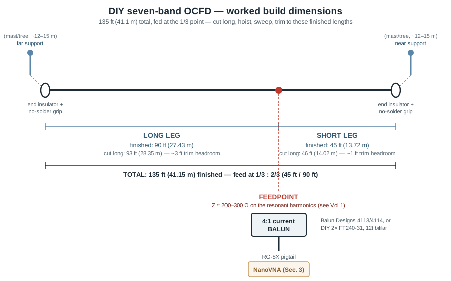
Table 1 — 2.2 Bill of materials
| Part | Specification | Source (verified) | Price (early July 2026) |
|---|---|---|---|
| Antenna wire | 14 AWG, 19×27 stranded copper, UV-resistant black PVC jacket, 150 ft spool | DX Engineering DXE-ANTW-150 — verified live listing | $49.99 |
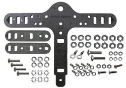
| Center-T + end insulator kit | EZ-BUILD® no-solder serpentine-grip center-T insulator + 2 matching end insulators + stainless hardware + crimp terminals; accommodates up to 4-gauge wire | DX Engineering DXE-UWA-KIT — verified live listing | $30.49 |
| 4:1 current balun | 1–54 MHz, 3 kW (1–35 MHz) / 2 kW (35–54 MHz), custom Fair-Rite low-permeability ferrite mix, SO-239 | Balun Designs Model 4113 — verified on manufacturer site | $82.95 |
| 4:1 current balun (higher-headroom alternative) | 1–54 MHz, 5 kW (1–35 MHz) / 3 kW (35–54 MHz), same ferrite family, SO-239 | Balun Designs Model 4114 — verified on manufacturer site | $98.95 |
| 4:1 current balun (DIY alternative) | 2× FT240-31 toroid cores, 12 turns #14 enamel or PTFE hookup wire, bifilar-wound, Guanella 1:4 topology (antenna-side windings in series, feedline-side in parallel) | Cores: Fair-Rite 2631803802 (DigiKey), 2× — verified live listing | 2× core $18.72 + enclosure/connector ≈ $25–35 |
| Halyard rope | 3/16″ double-braided Dacron/polyester, 770 lb break strength, UV-stabilized, 500 ft | DX Engineering / Synthetic Textile Industries SYN-DBR-187-500 — verified live listing | $85.99 (a 100–150 ft cut is all one OCFD needs; the asymmetric two-support geometry uses more rope than a simple center-hung dipole) |
| Coax pigtail | RG-8X, PL-259 to match the balun’s SO-239, ~1–3 m | Generic — any quality RG-8X with crimp or solder PL-259s; no single SKU is canonical here | ≈ $12–20 |
| NanoVNA | 10 kHz–1.5 GHz+, 4″ touchscreen, includes SMA OSL calibration kit, USB-C | Nooelec NanoVNA-H4 — verified on manufacturer site | $124.95 (one-time tool cost, not consumed per build) |
| Weatherproofing | Self-amalgamating rubber tape + vinyl overwrap | 3M Scotch 130C (rubber splicing tape) + 3M Super 33+ (vinyl electrical tape) — both standard, widely stocked | ≈ $15 combined |
Reading the table. The wire spool is sized with the OCFD’s asymmetric geometry in mind: 135 ft of finished antenna plus termination slack and trim headroom on both legs comfortably fits inside the 150 ft spool with a few feet to spare — there is no “buy two spools” math here the way there sometimes is on a longer doublet. The balun is again where the real cost-and-effort fork sits: $82.95 for a factory Balun Designs 4113 (3 kW below 35 MHz, which comfortably covers legal-limit SSB on every HF band this build targets) versus roughly $45–55 in parts for a DIY 2-core FT240-31 winding. A single toroid does not make a legitimate 4:1 current balun — the widely-published Guanella 1:4 designs (documented independently by multiple builders, including the widely-cited KB1LQC construction guide) require two separate cores, each wound with the same number of bifilar turns, with the antenna-side windings connected in series and the feedline-side windings connected in parallel; a single-core “4:1” that skips this is a common and well-documented DIY mistake. Twelve bifilar turns per core on FT240-31 is the commonly published starting point and the one this build uses; §2.3 gives the winding detail.
Total for a fully commercial-balun build: roughly $280 ($49.99 + $30.49 + $82.95 + $85.99 + $16 coax + $15 weatherproofing = $280.42, excluding the reusable NanoVNA) — comfortably inside the “$220–330” estimate, and toward the low end of it since the halyard spool is a bulk buy that covers this build with plenty left over for repairs or a second antenna. Swapping in the DIY balun trades roughly $40 in parts savings for a winding evening and a somewhat less certain choking-impedance curve than a lab-measured commercial part.
5.2.3 The DIY 4:1 balun — winding notes
If winding rather than buying: stack two FT240-31 cores (Fair-Rite 2631803802) and, on each core independently, wind 12 turns of a bifilar pair — two lengths of #14 enameled or PTFE-insulated wire run side by side through the core on every turn, exactly as in the classic “bifilar wound toroidal transformer” construction photograph every ham who has built a balun eventually recognizes. Once both cores are wound, the four winding pairs (two per core) are interconnected in the Guanella 1:4 pattern: the two windings that will face the antenna are connected in series (the finish of one to the start of the other), and the two windings that will face the 50 Ω feedline are connected in parallel (starts tied together, finishes tied together). The series antenna-side pair presents four times the impedance seen at the parallel feedline-side pair — the 4:1 transformation — while the current-balun topology (as opposed to a simpler voltage-type Ruthroff design) keeps common-mode current off the outside of the feedline shield, which matters enormously on an OCFD given how asymmetric the antenna’s two legs are.
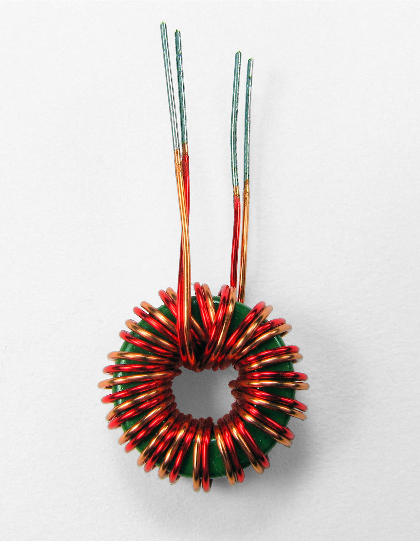
Pot the finished winding in a weatherproof enclosure (a Hammond 1590/1591-series polycarbonate box with cable glands is a common, generic choice with no single canonical SKU for this application) with SO-239 or N connectors for the feedline side and binding posts or crimp lugs for the antenna-side series connection. One important caveat this dive’s OCFD volume already flags: a 4:1 current balun at the feedpoint is correct for the plain OCFD this build targets, but is explicitly the wrong component if you are instead building toward a Carolina-Windom-style deliberate-vertical-radiator variant, which wants a voltage balun ahead of the radiating coax stub, not a current balun there — that variant’s design lives with the OCFD family theory in Vol 1, not in this parts list.
5.3 DIY build — construction, step by step
Cut the wires long. §2.2’s dimensions are the finished target: a 90 ft long leg and a 45 ft short leg. Cut a long leg at 93 ft (28.35 m) and a short leg at 46 ft (14.02 m) — a few percent over target on each, weighted slightly more toward the long leg because, as §4 develops, most of the fine trim on an OCFD happens there. The reasoning is the same one-directional logic every wire-dipole build in this hub follows: side cutters only shorten a wire, so any error in the offset math, an insulator that adds more end capacitance than assumed, or a support height that detunes the antenna, is recoverable by trimming further; a wire cut exactly to length that turns out short is not recoverable without a splice, and a spliced radiating element is a mechanical and RF headache on any band, worse on seven of them at once.
Terminate the ends. Thread each wire end through the DXE-UWA-KIT’s no-solder serpentine-grip end insulator per its instructions — the grip geometry holds the wire under tension without a solder joint. If using traditional ceramic egg or dogbone insulators instead, loop the wire end through the insulator’s eye, double back 12–15 cm, wrap 6–8 turns tightly around the standing wire, and solder the wrap; the doubled-back wrap carries the mechanical strain, the solder is corrosion insurance at the electrical joint.
Terminate the center. Each wire’s inboard end lands on the center-T insulator’s terminal — the DXE-UWA-KIT’s serpentine grip again needs no solder; a plain center insulator takes a soldered ring-terminal lug on each of its two stud terminals. The two legs meet only through the balun’s transformation, never by a direct jumper, and — because this is an off-center feed — the two legs’ termination points on the center-T are mechanically identical even though the wire lengths beyond them are very different; nothing about the center hardware itself needs to change from a symmetric dipole build.
Install the balun. A factory Balun Designs 4113 or 4114 bolts to the center insulator’s studs or its own mounting bracket and takes the coax pigtail on its SO-239. A DIY 2-core winding needs its series-connected antenna-side leads bonded to the center-insulator terminals and its parallel-connected feedline-side leads run to the SO-239 or N bulkhead connector, all inside the weatherproof enclosure from §2.3.
Add halyards and mount asymmetrically. Cut two lengths of the 3/16″ Dacron rope — one sized to reach from the long-leg end insulator to its support point and back down to a ground-level tie-off, the other for the short-leg end. Because the two legs are 90 ft and 45 ft, the two support points are necessarily at different distances from the feedpoint; a common deployment is an inverted-V-ish sloping flat-top with the long leg reaching a taller or more distant support and the short leg reaching a closer one, but a level flat-top between two supports at unequal horizontal distances from the feedpoint works just as well. Tie a stopper knot (figure-8-with-follow-through, or a bowline) at each insulator end.
Hoist and take a first sweep. Raise the antenna to 12–15 m (40–50 ft) — the general-purpose height this dive’s foundational volumes recommend for HF wire antennas — and connect the calibrated NanoVNA at the feedline’s shack end (calibrate before this step, not after; §4 covers it). Sweep the full HF range the antenna is meant to cover, 3–30 MHz at minimum, and read where each band’s SWR minimum actually sits.
Trim — mostly the long leg. OCFD trimming is deliberately uneven: because the long leg carries roughly twice the wire (and thus roughly twice the electrical length) of the short leg, most length adjustment happens there. If the 80 m resonance sits too high in frequency (antenna electrically short), lengthen the long leg; if too low, trim it. Work the long leg down to its 80 m target first, then check the higher-band harmonics — because the 1/3-point feed is self-consistent across the harmonic family, getting 80 m right on a correctly-proportioned antenna should bring 40/20/15/12/10 m close to their targets too. Only fine trim the short leg afterward, and only if a specific band still needs a small nudge that adjusting the long leg alone won’t reach.
Lock and weatherproof. Once the sweep lands within the tolerances §4 sets, apply 3M Scotch 130C self-amalgamating rubber tape to the balun-to-coax connector junction, then overwrap with 3M Super 33+ vinyl tape — the same two-layer combination (rubber for the seal, vinyl for UV protection) every wire-antenna build in this hub uses, because rubber tape alone degrades in sunlight and vinyl tape alone does not seal against water. Give the balun-to-coax junction particular attention on this build specifically: an OCFD’s balun carries power on seven bands rather than one, and any moisture intrusion at that connector accelerates corrosion under that heavier duty cycle.
5.4 Tuning with a NanoVNA — the multi-band sweep and trim
Calibrate first, at the feedpoint if you can reach it. The OSL (Open-Short-Load) sequence is unchanged from every other wire-antenna build in this hub: connect Open, select OPEN; connect Short, select SHORT; connect the 50 Ω Load, select LOAD; save the calibration. Calibrating at the antenna feedpoint gives the cleanest number; calibrating at the shack end of a known feedline instead means the feedline’s own loss and length are baked into the reference plane, which matters more here than on a single-band dipole because that baked-in error repeats across seven separate band readings rather than one.
Sweep the full HF range in one pass, then read each band’s minimum in turn. Set a span of at least 3–30 MHz (a 4″-screen NanoVNA like the H4 handles this in one sweep at reasonable resolution; NanoVNA-Saver on a laptop gives finer per-band resolution if the on-device screen is too coarse to read a 200 kHz-wide dip against a 27 MHz-wide span). Read the SWR or |S11| trace’s local minimum inside each amateur allocation separately — a multi-band antenna’s overall trace is not one smooth curve with one minimum, it is a family of local minima, one near each harmonic, with the SWR climbing steeply in the non-amateur territory between them. Return loss converts to SWR the same way it always does: SWR = (1+|Γ|)/(1−|Γ|) with |Γ| = 10^(−RL/20); a 9.5 dB return loss is exactly 2:1.
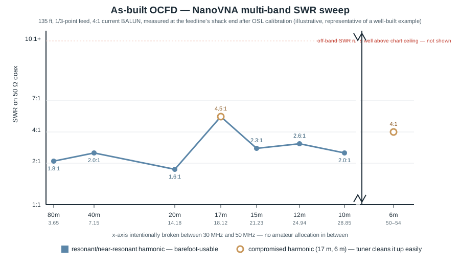
What a good final sweep looks like across all seven bands. For this 135 ft, 1/3-point-fed geometry with a properly wound 4:1 current balun:
- 80 m: minimum near 3.6–3.9 MHz, SWR roughly 1.6–2.0:1 — barefoot-usable.
- 40 m: minimum near 7.05–7.25 MHz, SWR roughly 1.8–2.2:1 — barefoot-usable.
- 20 m: minimum near 14.05–14.30 MHz, SWR roughly 1.5–1.8:1 — the strongest band on this geometry, consistent with 20 m being a favorable even-order harmonic of the 1/3-offset feed.
- 17 m: SWR generally 3–5:1 across the band, no clean minimum — compromised; a tuner cleans it up in seconds, and this is the band most builders find least satisfying barefoot.
- 15 m: minimum near 21.0–21.45 MHz, SWR roughly 2.0–2.6:1 — usable, sometimes described as a “bonus” band beyond the OCFD’s core marketed coverage, and worth checking even if you built expecting only 7 clean bands.
- 12 m: minimum near 24.89–24.99 MHz, SWR roughly 2.2–2.8:1 — usable.
- 10 m: minimum near 28.0–29.0 MHz, SWR roughly 1.8–2.2:1 — usable, and often the widest 2:1 window of any band on this build because of #14 wire’s inherently low Q at 10 m frequencies.
- 6 m: SWR generally 3–5:1 across 50–54 MHz, no clean minimum — compromised in the same way as 17 m; the antenna is operating at a very high harmonic order here, the pattern is a complex multi-lobed mess, but a tuner still gets useful power onto the wire.
Trim procedure. Lower the antenna, adjust the long leg first — a few tens of centimeters moves the 80 m minimum meaningfully, and because the feed ratio is self-consistent across harmonics, correcting 80 m tends to pull 40/20/15/12/10 m toward their targets simultaneously. Re-terminate, re-hoist, re-sweep. Two to four iterations is typical; if 80 m converges cleanly but 20 m and higher stay stubbornly off by more than roughly 100–150 kHz after several long-leg trims, suspect the feed ratio itself rather than pure length — a short leg cut to the wrong fraction of the total (not exactly 1/3) will show exactly this symptom, since the higher harmonics are more sensitive to the ratio than the absolute length. Only fine-trim the short leg once the long leg has the low bands converged.
The common-mode check, unchanged from single-band builds but higher-stakes here. Grab the coax a meter below the balun and flex or re-route it while watching the sweep. If any band’s SWR minimum shifts, common-mode current is riding the shield rather than being properly choked by the balun — Vol 1 covers why an OCFD’s inherent asymmetry makes this check more important than on a symmetric dipole, not less: the very asymmetry that lets one feed point work across seven harmonically-related bands also means the two legs never balance each other’s common-mode contribution the way a geometrically symmetric dipole’s legs do, so the balun is carrying a heavier common-mode-suppression burden by design.
5.5 Commercial buys — ranked, with price tiers
For the builder who would rather spend money than an evening — or who wants a factory-tuned reference to sanity-check a homebrew build against — the following are current, verified multi-band dipole products as of early July 2026, spanning every design family this dive covers: OCFD, parallel/trap, and tuner-fed. Every product below was checked against a live manufacturer or authorized-dealer listing; the one exception (Radio Works) is flagged explicitly.
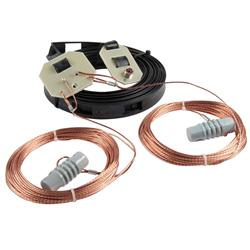
Table 2 — 5. Commercial buys — ranked, with price tiers
| Tier | Product | Design family | Bands | Price (early July 2026) | Notes |
|---|---|---|---|---|---|
| Budget | MFJ-1778 | G5RV-style tuner-fed (Vol 3) | 80–10 m, tuner-dependent | $89.95 (verified, MFJ direct) | The real Original G5RV, 102 ft plus 31 ft of 450 Ω ladder line. A tuner is mandatory off the 20 m design band; treat “80–10 m” as “usable with a tuner,” not “resonant.” |
| Budget | W5GI Mystery Antenna, 80/6 m (K4TR) | Multi-section collinear (Vol 3-adjacent — a folded/collinear doublet variant) | 80–6 m | $115.99 (verified, K4TR — the design’s own trademark holder and USPTO-registered manufacturer) | Three half-waves in phase on 20 m with a half-wave line-section transformer; a six-lobe pattern on 20 m with broadside gain. Fully assembled, #14 stranded UV-jacketed wire, 2 kW rated. |
| Budget-mid | Alpha Delta DX-EE | Parallel/fan (Vol 2) | 40/20/15/10 m (tuner needed on 15 m) | $195.99 (verified, DX Engineering) | 40 ft overall, 12 AWG solid copper, 1000 W PEP/CW. The compact end of the Alpha Delta parallel-dipole line — a genuine fan dipole in a single-box product. |
| Mid | Alpha Delta DX-CC | Parallel/fan (Vol 2) | 80/40/20/15/10 m (tuner needed on 15 m) | $209.99 (verified, DX Engineering) | 82 ft overall, DELTA-C center insulator with built-in static protection, 1000 W PEP/CW. The best-known no-trap parallel-dipole product on the US market; other retailers list it as low as $194.95, so shop around within a narrow band. |
| Mid | Buckmaster DX-OCF | OCFD (Vol 1) | 80/75, 40, 20, 17, 12, 10, 6 m | $319.00 (verified, DX Engineering) | 135 ft, 90/45 ft legs — the exact reference geometry §2 of this volume builds from. Ships fully assembled with a 300 W balun; a tuner may still be wanted for the last few kHz of match on some bands. |
| Premium | Buckmaster DX-OCF-HP | OCFD (Vol 1) | 80/75, 40, 20, 17, 12, 10, 6 m | $429.00 (verified, DX Engineering) | Identical antenna to the DX-OCF above with a 3,000 W-rated balun substituted — the correct choice for a legal-limit amplifier station running CW or digital modes at high duty cycle, where §2.2’s 3 kW Balun Designs 4113 would also be an appropriate DIY-balun target power. |
| Premium (approximate) | Radio Works Carolina Windom, 80 m family (CW-80 / CWS-80 Special) | OCFD + deliberate-radiating-coax-stub variant (Vol 1) | 80–10 m | Not independently verified — the manufacturer’s own site (radioworks.com) did not resolve at time of writing. A UK authorized dealer listed the CWS-80 Special at £89.95 (a compact 66 ft version); historically the full-size CW-80 (133 ft) has run $120–270 USD in the North American market depending on wire (bare copperweld vs. insulated) and balun options. Treat these figures as dated and re-confirm before ordering. | The original W2DU-designed deliberate-radiating-coax-stub OCFD variant; Vol 1 covers why this design’s claimed low-angle DX advantage is modest and controversial compared to a plain, well-choked OCFD. |
What to avoid. Unbranded “seven-band miracle antenna” listings that don’t publish a balun power rating or ferrite mix — a balun you can’t size against your own power level and duty cycle is a balun that will surprise you the first time you run a long CW or FT8 session at legal limit. Listings advertising “no soldering, no crimping, anywhere” are worth a skeptical look at the actual termination photos — the DXE-UWA-KIT’s serpentine no-solder grip verified in §2.2 is a legitimately engineered mechanism, but a generic “just twist the wires” termination on an unbranded listing is not the same claim wearing the same words, and will not survive years of wind flex on an antenna this length. And any “seven-band, no tuner needed anywhere” claim should be read against §4’s own honest sweep data above — 6 of seven bands barefoot-usable is what a well-built OCFD actually delivers; the other 2 need a tuner, and a listing that promises otherwise is marketing, not physics.
5.6 Companion gear
The balun/tuner choice is the real fork in this dive, not an afterthought. An OCFD’s 4:1 current balun (§2) and a doublet’s balanced tuner (Vol 3) solve the same underlying problem — getting a non-50-Ω, frequency-varying feedpoint down to something a rig accepts — with opposite philosophies: the balun bets on the antenna geometry doing most of the matching work across all seven bands from one fixed transformation ratio, while the tuner bets on doing fresh matching work on the bench for every band, accepting whatever impedance the antenna presents. If you already own a quality balanced tuner (Palstar AT2K, $749.95–$795 depending on retailer — verified — MFJ-976, or a vintage Johnson Matchbox), a doublet may be the better companion antenna for it than the wire this volume builds; if you’d rather never touch a tuner knob on 6 of seven bands, the OCFD is the right match for a “plug coax into the rig” operating style.
Ladder line vs. coax — a choice this build doesn’t actually face, but its sibling volume’s antenna does. The OCFD in this volume is deliberately coax-fed end to end; nothing about its BOM involves ladder line. Vol 3’s doublet is the antenna in this dive that lives or dies on low-loss balanced feedline — real 450 Ω ladder line (DX Engineering’s DXE-LL450 window-line family is a verified, currently-sold product) loses a small, SWR-independent amount over a run, where coax’s loss climbs sharply with SWR. If a later addition to the station is a doublet rather than another OCFD, that’s the point at which ladder line and a feed-through panel enter the picture; this build’s coax-only feed doesn’t need either.
Mast or dual support. The OCFD’s asymmetric geometry (§3) genuinely needs two support points at different distances from the feedpoint, unlike a level dipole’s matched pair — a single elevated apex with the balun at the top and both legs sloping down to ground-level anchors (an inverted-V-style deployment) works and needs only one tall support; a level flat-top needs two, sized for 90 ft and 45 ft of horizontal run respectively. A Spiderbeam 12 m HD fiberglass telescoping pole (a real, currently-sold product from the exclusive North American distributor Vibroplex, among others) is a common single-support choice; a tree limb with a properly halyarded support point works just as well for either leg.
Halyards. §2.2’s verified SYN-DBR-187-500 Dacron spool covers this build with plenty of rope left over — plan on roughly double the halyard length of a symmetric dipole of the same overall length, since the two unequal legs need two separately-sized halyard runs rather than one matched pair. Dacron’s near-zero stretch under load matters here exactly as it does on every wire antenna in this hub: a stretching halyard sags and slowly detunes the antenna over weeks, and on a seven-band antenna that detuning shows up as a slow drift across every one of those sweep minima rather than just one.
A second common-mode choke at the shack entry. Even with a properly wound 4:1 current balun at the feedpoint, a string-of-beads or air-core choke at the point the feedline enters the shack is recommended — it catches whatever common-mode current the OCFD’s inherent leg-asymmetry lets slip past the feedpoint balun over a long feedline run, exactly the mechanism §4’s flex-the-coax check is testing for.
Lightning protection. The same polyphaser-style arrestor and single-point-ground topology every wire antenna in this hub uses applies without modification here; the OCFD’s extra band coverage doesn’t change the lightning-protection requirement at all.
5.7 Gotchas and myths
“An seven-band OCFD needs no tuner on any band” is the single most common overclaim in this dive. §4’s own sweep data is the honest answer: 6 of seven bands barefoot-usable at a reasonable SWR, 2 (typically 17 m and 6 m on this geometry) needing a tuner. “No tuner needed on most bands” is accurate and still genuinely excellent performance for one feedline; “no tuner needed, period” is marketing.
“The feed offset is 14% from the end” is a figure that shows up in some older literature and describes a genuinely different, older antenna — the original 1929 Windom was a single-wire feed with a grounded return and no balun, fed at roughly that fraction. The modern Buckmaster-style OCFD this volume builds is verified, from the actual current commercial product, to feed at the 1/3 point (33%:67%, not 14%:86%). Conflating the two is an easy mistake to make since both are called “off-center fed,” but they are mechanically and electrically different antennas.
“The BALUN ratio is exact” is false in the way that matters for design, not just in the abstract. A “4:1” current balun is nominally 4:1 but drifts meaningfully across a 10:1 frequency span (3.5–30 MHz, before even considering 50–54 MHz), and that drift is a real contributor to why some bands on an OCFD sweep cleaner than others even on a geometrically perfect build. If §4’s sweep shows 80 m and 40 m converging nicely but the higher bands staying stubbornly off after repeated trims, the balun’s high-frequency behavior — not the wire length — is the first thing worth suspecting.
“A single toroid can be a 4:1 current balun” is a specific, well-documented DIY mistake. §2.3’s Guanella 1:4 topology needs two separate cores wound and interconnected in series-on-the-antenna-side, parallel-on-the-feedline-side; a single core wound for a “4:1” ratio without that two-core series/parallel structure will not deliver a proper current-balun’s common-mode rejection, and on an antenna as asymmetric as an OCFD, that rejection is not optional.
“My rig shows an acceptable SWR, so all seven bands must be working” conflates the shack-end reading with the feedpoint reality exactly as it would on any wire antenna — a lossy feedline attenuates the reflected wave on its way back and makes a mismatched load look better than it is at the transmitter end. §4’s instruction to calibrate at the feedpoint whenever reachable exists precisely because a seven-band antenna gives you seven separate chances to be fooled by this, not just one.
“More bands always means a better antenna” is the framing error this entire dive has been pushing back against, volume by volume. An OCFD covering 6 clean bands and 2 compromised ones is not automatically a better choice than a single-band dipole that covers one band cleanly, or a fan dipole (Vol 2) covering three bands cleanly with no compromise at all — “more bands” is a genuine convenience that trades against pattern symmetry, balun heating under heavier duty cycle, and per-band efficiency, and the right choice depends on which bands you actually operate, not on maximizing the band count on a spec sheet.
5.8 Where this volume — and this dive — hands off
This volume closed the multi-band dipole dive by putting the first four volumes’ catalog of solutions onto a workbench and a shopping list. It gave a complete, real-parts bill of materials and construction sequence for the Buckmaster-style seven-band OCFD — a verified $49.99 wire spool, a verified $30.49 no-solder insulator kit, a verified $82.95 factory 4:1 balun (or its two-core DIY alternative) — with the feedpoint offset math corrected against the actual current commercial reference design rather than repeating an older, unverified figure. It formalized the NanoVNA multi-band sweep-and-trim workflow: calibrate, sweep the full HF range in one pass, read each band’s own local minimum rather than expecting one smooth curve, trim the long leg first, and re-sweep — converging on a build that delivers around six barefoot-usable bands (15 m often among them, as the bonus beyond Buckmaster’s marketed seven) and a couple of tuner-friendly ones, matched against what the harmonic theory in Vol 1 predicts. It surveyed the commercial alternative across every design family this dive covers — G5RV-style tuner-fed, collinear/doublet, parallel/fan, and OCFD — at three verified price tiers, from an $89.95 MFJ-1778 through a $319.00 Buckmaster DX-OCF to a legal-limit-rated $429.00 DX-OCF-HP. And it closed with the companion gear and the myths — the false “14% offset,” the false “no tuner ever,” the real single-toroid balun mistake — that separate a multi-band build that performs for two decades from one that quietly underperforms its own geometry.
Zooming out, this volume is also the last of the five that make up the multi-band dipoles dive. Vol 1 established why a resonant dipole is single-band by construction and how shifting the feed off-center exploits the harmonic current-node structure to fix that, landing on the OCFD and Carolina Windom as the dominant modern answer. Vol 2 covered the two brute-force alternatives that keep every band fully resonant at the cost of mechanical complexity or per-band loss: the fan dipole’s parallel resonators and the trap dipole’s frequency-selective LC tanks. Vol 3 took the opposite philosophy — abandon resonance, feed a long wire with low-loss balanced line, and let a tuner do the matching — covering the doublet, the G5RV, and the optimized ZS6BKW variant. Vol 4 covered the two designs that solve the multi-band problem by physical reconfiguration rather than clever feed or matching: the linked dipole’s insertable band-change jumpers, and the cage dipole’s wide-bandwidth single-band answer to the same underlying “more usable spectrum from one wire” impulse. And this volume put all of it on a spool of wire, a NanoVNA, and — for the reader who would rather buy than build — a dated, verified shopping list spanning every family the first four volumes described.
The single-band half-wave dipole (the sibling dive) is the reference antenna the rest of the Antennas hub measures everything against; this dive’s multi-band variants are what most operators actually end up building, because most operators want more than one band from one feedline and one antenna. The matching-network theory this dive leaned on throughout — the full balun/unun family beyond the 4:1 current design built here, and the balanced-tuner alternative the doublet volume depends on — lives in the hub’s dedicated matching-network dives; the measurement theory behind the NanoVNA workflow lives in the hub’s measurement cluster; and the physical-deployment concerns touched only briefly here (masts, weatherproofing, grounding, lightning) each have a full dedicated dive of their own. This volume points to all of them rather than reproducing them, consistent with the whole hub’s cross-linking discipline.
5.9 Resources
- ARRL Antenna Book (25th+ ed.), the multi-band and off-center-fed dipole construction chapters — the canonical amateur reference for OCFD geometry, balun sizing, and the harmonic-impedance tables this build’s offset math draws on.
- DX Engineering — https://www.dxengineering.com — the source verified for the wire, insulator-kit, halyard-rope, Buckmaster DX-OCF/DX-OCF-HP, and Alpha Delta DX-CC part numbers and prices in Sections 2 and 5.
- Balun Designs — https://www.balundesigns.com — the source verified for the Model 4113 and Model 4114 4:1 current balun specifications and prices.
- Fair-Rite Products ferrite data sheet (mix 31) — the source for the FT240-31 core specification cited in Section 2; the broader mix selection is developed fully in the single-band dipole dive’s balun volume.
- MFJ Enterprises — https://mfjenterprises.com — the source verified for the MFJ-1778 G5RV price.
- K4TR Antenna Mfg — https://www.k4tr.com — the source verified for the W5GI Mystery Antenna’s current pricing; the only manufacturer explicitly endorsed by the antenna’s original designer (W5GI) and holding the design’s USPTO registration.
- The widely-published Guanella 1:4 current balun construction guides (e.g., the KB1LQC design writeup, and G0UIH’s Q82.uk balun-transformer notes) — the source for the two-core, bifilar, series-antenna/parallel-feedline winding topology in Section 2.3; independently cross-checked against multiple builder writeups rather than a single source.
- NanoVNA-Saver (PC companion software) — https://github.com/NanoVNA-Saver/nanovna-saver — the natural next step once the on-device sweep in Section 4 needs finer per-band resolution than a 4″ screen comfortably shows across an seven-band, 3–54 MHz span.
- The hub’s dedicated matching-network dives (BALUNs & UNUNs, Antenna Tuners) — the full transmission-line-transformer theory and the balanced-tuner alternative this volume’s companion-gear section pointed to rather than reproduced.
- The hub’s measurement cluster (NanoVNA deep dive, other analyzers, power/SWR measurement) — the full instrument-level treatment behind the workflow Section 4 used at the level this dive needed.
- The single-band dipoles dive, especially its own DIY-build-and-buy closing volume — the sibling reference this volume’s structure mirrors, and the antenna family every multi-band variant in this dive is ultimately a compromise away from.
Comments (0)