Multi-Band Dipoles · Volume 1
The Multi-Band Problem & the Off-Center-Fed Dipole
Why a resonant dipole is single-band by construction, the four families of solution, and the off-center-fed dipole (OCFD / Carolina Windom) — feedpoint, BALUN, harmonic pattern behavior, and the deliberately-radiating feedline
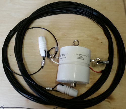
1.1 About this volume
Single-Band Dipoles established the clean reference case: a half-wave element fed at the center, resonant at one frequency, 73 + j0 Ω at that frequency and increasingly reactive on either side of it. That antenna is a superb single-band tool and a poor multi-band one, and the reason is structural rather than incidental — it is baked into the standing-wave current distribution itself, not an accident of a particular build. Real operating life wants more than one band from a lot that will support exactly one horizontal wire, and the amateur community has spent ninety-odd years working out how to get it.
This volume opens the five-volume Multi-Band & Specialty Dipoles dive with the two pieces that frame everything downstream: first, a precise account of why the single-band constraint exists and what the four structurally distinct families of workaround actually trade away to lift it; second, a full engineer-grade treatment of the family that currently dominates the residential multi-band market — the off-center-fed dipole (OCFD) and its best-known commercial descendant, the Carolina Windom. The remaining families — parallel and trapped resonators, tuner-fed nonresonant doublets, and switched/linked designs — get their own volumes, forward-referenced here rather than pre-empted: Vol 2 covers the fan dipole and the trap dipole, Vol 3 covers the doublet and the G5RV/ZS6BKW family, Vol 4 covers the linked dipole and the wide-bandwidth cage dipole, and Vol 5 closes the dive with a DIY build, a commercial-buy survey, companion gear, and a gotchas list that spans all four families.
The OCFD earns the full-volume treatment here because it is, by a wide margin, the multi-band wire antenna most likely to end up in a working ham’s backyard: one wire, one feedline, no ladder line into the shack, no traps to burn out, and (on most of its bands) no tuner. Understanding exactly what the off-center feed buys you — and exactly what it costs — is the single most useful piece of multi-band antenna literacy this dive has to offer.
1.2 Why a resonant dipole is single-band by construction
Single-Band Dipoles Vol 1 §2 derived the standing-wave picture for a center-fed half-wave element: a half-cosine current distribution with a maximum at the feedpoint and nulls at the two open ends, I(z) ≈ I₀·cos(βz). That derivation assumed the element was exactly a half-wavelength long. Nothing in the physics stops you from driving the same wire at a different frequency, but the boundary conditions change the standing wave that results, and the consequences for feedpoint impedance are severe enough to make the antenna practically single-band.
Hold the element’s physical length fixed at L, cut for a half-wavelength at some design frequency f. Drive it at a harmonic n·f. The wire is now electrically n half-wavelengths long, and the boundary conditions — current zero at both open ends — are still satisfied by a standing wave, but that standing wave now has n current lobes distributed along the element instead of one. The center of the wire, which was the single current antinode at the fundamental, is:
- a current antinode (low impedance, resonant-like) when
nis odd — the standing wave has an odd number of half-cycles, and an odd number of half-cycles always places a current maximum at the geometric center by symmetry; - a current node (high impedance, close to an open circuit) when
nis even — an even number of half-cycles places a current null, not a maximum, exactly at the center, because the center now falls at the boundary between two mirror-image lobes.
This is the mechanism the antenna literature shorthands as “a center-fed dipole is resonant at odd harmonics and presents a high-impedance, open-circuit-like feedpoint at even harmonics,” and it is not a rule of thumb — it falls directly out of the mode structure of a wire with fixed open ends. For a residential 80 m dipole (design frequency ≈ 3.5 MHz), the odd harmonics land at 10.5, 17.5, and 24.5 MHz — close to (though not exactly on) the 30 m, 17 m, and 12 m WARC bands — where the center-fed antenna presents a moderate, workable impedance. The even harmonics land at 7.0, 14.0, 21.0, and 28.0 MHz — squarely on 40 m, 20 m, 15 m, and 10 m, the most-used HF bands — where the same antenna presents a feedpoint impedance of several kilohms, deeply reactive, and effectively unusable without a tuner absorbing the mismatch. This is the even-harmonic high-Z problem, and it is the single fact that makes “just feed my 80 m dipole on every band” a tuner-mandatory proposition rather than a multi-band antenna in its own right.
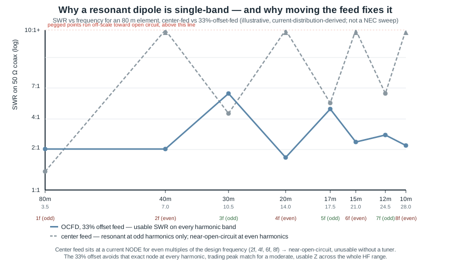
The figure makes the case visually: the dashed center-feed trace is resonant (or near enough) at the odd-harmonic bands and pinned toward infinite SWR at the even-harmonic bands, while the solid off-center trace never approaches resonance as sharply as the center-fed dipole does at its one design frequency, but it never runs off the chart either — it sits in a broadly usable 1.5:1–4:1 band at every harmonic shown. That flattening is the entire mechanism behind every off-center-fed design discussed in this volume, and it costs something specific and quantifiable, which §4–§5 work out in detail.
1.3 Four families of solution
Beyond moving the feedpoint, the amateur community has three structurally distinct other ways to put more than one band on a single length of wire, and it is worth naming all four as a taxonomy before diving into any one of them, because the four are genuinely different engineering trades rather than four flavors of the same idea.
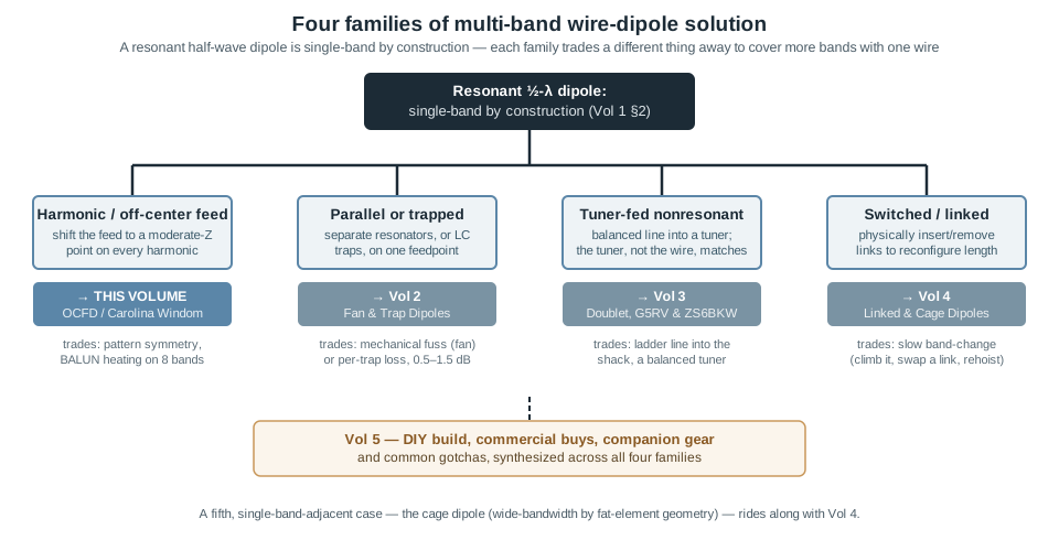
Harmonic / off-center feed (this volume). Shift the feedpoint away from the geometric center to a position that presents a moderate, roughly-constant impedance across several harmonics simultaneously, rather than the alternating “resonant / open-circuit” pattern a center feed produces. The OCFD and the Carolina Windom are the entries in this family; §4 onward is a full treatment.
Parallel or trapped resonators (Vol 2). Instead of reshaping one element’s impedance behavior, put multiple resonant structures on a common feedpoint. A fan dipole hangs a separate full-size half-wave wire for each band off the same feedpoint, each one behaving — electrically — almost exactly like a standalone single-band dipole, at the cost of mechanical interaction between the wires during tuning. A trap dipole achieves a similar effect with a single tapered wire by inserting parallel-resonant LC traps that act as a near-open-circuit at their design frequency, electrically shortening the antenna band-by-band, at the cost of some real dissipative loss and narrower per-band bandwidth (Vol 2 §6 quantifies the loss against W8JI’s measured data, which is generally far lower than the “about a dB per trap” folklore).
Tuner-fed nonresonant (Vol 3). Give up on the antenna itself presenting anything close to 50 Ω on any band, feed it with low-loss balanced (ladder) line instead of coax specifically because ladder line’s loss stays low even at very high SWR, and let an external balanced antenna tuner do all of the impedance transformation at the shack end. The doublet is the general case; the G5RV and its optimized derivative the ZS6BKW are specific wire-plus-ladder-line lengths whose harmonic impedances happen to land in a tuner-friendly range on more bands than an arbitrary length would.
Switched / linked (Vol 4). Physically change the antenna’s electrical length for each band by inserting or removing conductive links partway down each leg, trading a few minutes of band-change time (lower the antenna, move a link, re-hoist) for full single-band-dipole efficiency and pattern on whichever band is currently configured — no traps, no BALUN compromise, no off-resonance feed. Vol 4 also covers the cage dipole, which is single-band rather than multi-band but belongs in the same conversation because it solves an adjacent problem — buying enough bandwidth from a fat multi-wire element that an entire wide amateur band (80 m, 160 m) sits inside a 2:1 SWR window without any band-switching machinery at all.
Every one of these trades something specific: the OCFD trades pattern symmetry and pushes some power into BALUN heating; the fan/trap family trades mechanical complexity or per-trap dissipation; the doublet trades a balanced tuner and a ladder-line run into the shack; the linked dipole trades band-change speed. None of the four is a free lunch, and picking among them is really picking which cost you can live with for your lot, your budget, and your operating habits — the decision matrix in Vol 5 lays the four out side by side once all are covered in depth.
1.4 The off-center-fed dipole: geometry and theory
The OCFD is, mechanically, the same flat-top wire as a single-band dipole — two straight legs, two end insulators, a horizontal (or gently sloped) run between two supports — with exactly one change: the feedpoint sits at a fixed fractional distance from one end rather than at the midpoint. The wire is cut to resonate as a half-wave at some lowest design frequency (conventionally 80 m for a full-size residential build), and the feed is inserted at approximately the 1/3 point: one leg (the “short leg”) runs from the feedpoint to the nearer end and carries roughly a third of the total length, the other (the “long leg”) carries the remaining two-thirds.
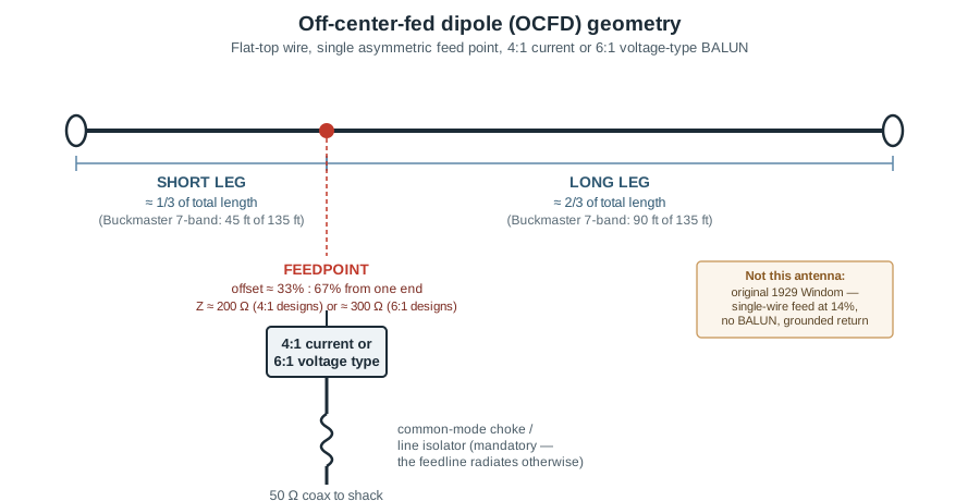
The design literature is not perfectly uniform on the exact fraction — published tutorial designs range from roughly 22.5% to 36% depending on which set of bands the author is optimizing for — but 1/3 : 2/3 is the figure that recurs across both independent DIY designs and the dominant commercial product line (Buckmaster’s 7- and 8-band OCF antennas use an exact 45 ft : 90 ft split on their 135 ft model, precisely a 1:2 ratio). This volume treats 1/3 as the reference design point and calls out the handful of bands where any single-offset choice inevitably compromises (§6).
It is worth being explicit about a point of genuine historical confusion, because the antenna’s own name invites it: the original Windom antenna, described by Loren Windom (W8GZ) in the September 1929 issue of QST, was a single-wire-fed Zepp-type antenna tapped at roughly 14% off-center and connected directly to an unbalanced single-wire feeder run into the shack, with no BALUN at all and the station ground serving as the return path. That is a different antenna from the modern OCFD discussed in this volume — a twin-conductor, BALUN-fed dipole with no dependence on an RF ground — and the two get conflated regularly in casual ham literature (some secondary sources have applied the original Windom’s 14% figure to the modern commercial OCFD, which is incorrect; the Buckmaster product’s verified dimensions are the 1:2/33% split above). The “Windom” name survives in “Carolina Windom” (§8) purely by lineage, not by sharing the feed fraction, feed topology, or ground dependence of Loren Windom’s 1929 design.
Why does 1/3 work where center feed fails? Return to the mode picture in §2: at any harmonic n, the standing wave has n current lobes and n+1 nodes distributed evenly along the wire’s electrical length. A feedpoint at a fixed fractional position — rather than always at the exact center — will, for most values of n, land somewhere between a lobe peak and an adjacent node rather than exactly on either one. The impedance at that point is neither the very-low resistive value at a peak nor the very-high reactive value at a node; it is a moderate value that varies band-to-band but stays within an order of magnitude across the whole HF range. The price for that consistency is that the antenna is never as cleanly matched at any single harmonic as a center-fed dipole is at its one design frequency — the 1/3 offset is a broadband compromise, not a resonance in the classical center-fed sense.
1.5 Feedpoint impedance and the BALUN
The feedpoint impedance the 1/3 offset produces is not a single fixed number — it depends on which harmonic you’re on, the exact offset fraction chosen, and the height and surroundings of the installation — but the design literature converges on two commonly-quoted design centers, and the choice of BALUN ratio tracks which one a given design targets:
- ≈ 200 Ω, matched with a 4:1 current BALUN to 50 Ω coax. This is the figure most independent DIY and tutorial designs (and several kit vendors) target at the 1/3 offset, and it is the pairing this volume’s companion build guide in Vol 5 uses.
- ≈ 300 Ω, matched with a 6:1 (often voltage-type) BALUN to 50 Ω coax. This is the pairing Buckmaster’s commercial 7- and 8-band OCF antennas use — the product literature specifies a custom-wound, epoxy-potted 6:1 autotransformer at the feedpoint of the 135 ft (7-band) and 270 ft (8-band) models.
Both pairings are real, both are in wide production and home-brew use, and neither is “the” correct OCFD impedance — the offset fraction sets a range of feedpoint impedances across the harmonic bands, and the BALUN choice determines which nominal center of that range gets transformed cleanly to 50 Ω. A build note worth internalizing from Vol 5 in advance: a “4:1” or “6:1” BALUN is a nominal ratio, not an exact one. Ferrite-core current transformers hold their turns-ratio impedance transformation well near their design center but drift by as much as ±25% across a 10:1 frequency span (3.5–30 MHz), which is itself part of why the SWR at each harmonic band varies as much as it does even on a geometrically ideal OCFD — the BALUN’s departure from its nominal ratio at the band edges is baked into the same curve that the offset geometry produces.
The current BALUN topology (as opposed to voltage) is the correct choice for an OCFD specifically because the antenna’s leg asymmetry makes it an inherently unbalanced structure feeding a nominally balanced dipole — the short and long legs do not present mirror-image impedances to ground, so common-mode current on the outer surface of the coax shield is actively encouraged rather than merely tolerated. A current BALUN forces the two output currents into forced equality regardless of that imbalance, which is the mechanism that keeps common-mode current off the feedline in the first place. It is worth noting that the flagship commercial OCFD — the Buckmaster line (§6) — actually uses a 6:1 voltage-type autotransformer at its ≈300 Ω design center rather than a current BALUN, a choice several authorities (W8JI among them) specifically caution against on exactly this asymmetric-antenna common-mode ground; the DIY-favored pairing of a 4:1 current BALUN at the classic 1/3 offset is the more defensible engineering choice, and it is the one the build in Vol 5 follows.
That mechanism is not perfect, and this is the single most important practical point in this section: a common-mode choke (line isolator) at the shack entry, in addition to the BALUN at the feedpoint, is not optional on an OCFD. Any common-mode current that gets past the feedpoint BALUN flows down the outside of the coax shield exactly like current on a third, uncontrolled radiating element — it distorts the pattern, it couples RF into the shack, and on receive it imports local electrical noise picked up along the entire feedline run. A second choke (a string-of-beads or wound air-core CMC) at the point where the coax enters the operating position kills whatever the feedpoint BALUN let through. This point is not unique to the OCFD — Single-Band Dipoles Vol 2 makes the same case for a plain center-fed dipole — but it is more important here, because the OCFD’s inherent asymmetry manufactures more common-mode current to begin with than a symmetric dipole does. The Carolina Windom variant in §8 goes a step further still and turns this same mechanism into a deliberate design feature rather than a nuisance to be suppressed.
1.6 Band coverage: the classic 1/3 OCFD vs the commercial Buckmaster design
Two design points recur in the literature, and they are worth distinguishing because their band-coverage claims differ:
The “classic” DIY/tutorial 1/3-offset OCFD — an 80 m-cut wire, 1/3 : 2/3 feed, 4:1 current BALUN, ~200 Ω design center — is documented in independent build guides as covering 80, 40, 20, and 10 m with usable (sub-3:1) SWR without a tuner, with the remaining HF bands needing a tuner to clean up. This is the four-band coverage this volume treats as the honest baseline claim for a from-scratch build at the 1/3 point.
The commercial Buckmaster OCF product line targets more bands from the same basic geometry by combining the 1/3 offset with a 6:1 balun and careful per-model length tuning:
Table 1 — The commercial Buckmaster OCF product line targets more bands from the same basic geometry by combining the 1/3 offset with a 6:1 balun and careful per-model length tuning
| Model length | Legs (short / long) | Balun | Bands claimed (no tuner) |
|---|---|---|---|
| 135 ft (41.1 m) — “7-band” | 45 ft / 90 ft | 6:1 voltage, potted | 80, 40, 20, 17, 12, 10, 6 m |
| 270 ft (82.3 m) — “8-band” | 90 ft / 180 ft | 6:1 voltage, potted | 160, 80, 40, 20, 17, 12, 10, 6 m |
| 68 ft (20.7 m) — compact | proportional | 6:1 voltage, potted | 40, 20, 10, 6 m |
The vendor’s per-model claims are the manufacturer’s stated coverage, reproduced here from the product documentation rather than independently re-derived; treat “no tuner required” as the vendor’s specification and verify SWR at your own installation height and surroundings before assuming it transfers unchanged — ground proximity and support geometry both shift the feedpoint impedance from the free-space design values, exactly as they do for a plain single-band dipole (Single-Band Dipoles Vol 3).
Both design points share the same underlying compromise pattern regardless of which specific bands the marketing highlights: some harmonic bands land close to a lobe peak of the offset feed’s standing wave and show clean, low SWR; others land close to a node and show markedly worse SWR, even though none run all the way to the near-open-circuit condition a center feed produces at its even harmonics. Independent modeling literature on the offset-feed problem is explicit that no single offset fraction avoids a compromised band entirely — one widely cited figure notes that a 33% offset leaves 30 m and 15 m with problematic near-zero-current conditions at the feedpoint, while a 25% offset instead compromises 20 m and 10 m. Which bands are “the good ones” and which are “the compromised ones” is a function of the specific offset chosen, not a universal property of “OCFD” as a category — a claim of “8 clean bands, no tuner, ever” from any vendor or design should be read skeptically until you’ve seen the actual SWR sweep for that specific geometry.
1.7 Radiation pattern across the harmonic bands
On its lowest design band — where the offset-fed element is still, to a first approximation, a single half-wave radiator — the OCFD’s far-field pattern is the same broadside figure-eight every half-wave dipole produces, with the asymmetric feed shifting the pattern’s null depth and symmetry only slightly relative to a center-fed element on the same band. As frequency climbs through the harmonics, though, the element becomes electrically several half-wavelengths long, and the radiation pattern does what any multi-wavelength wire’s pattern does: it fragments into multiple main lobes, the number and angle of which grow with the harmonic number. A wire that is 2.5 electrical wavelengths long (roughly where a 33 m OCFD sits on 20 m) already shows on the order of half a dozen lobes rather than a clean figure-eight, most of them off-broadside, with the strongest lobes canted a characteristic 15–30° from the wire axis rather than perpendicular to it.
This lobing is not a defect unique to off-center feeding — a plain center-fed dipole run on a harmonic band does exactly the same thing, because the lobe fragmentation is a property of how long the wire is in wavelengths, independent of where the feed sits. What the off-center feed changes is only the impedance at each harmonic, not the current distribution’s overall shape (beyond the local perturbation right at the asymmetric feedpoint), so the pattern-fragmentation story for an OCFD on 20 m is essentially the same story as for any 2.5λ wire on the same frequency. The practical consequence worth internalizing: “the OCFD’s pattern is the same on every band” is false, and it should not be marketed as an omnidirectional-equivalent multi-bander. The design does deliver usable gain in most azimuth directions on most bands because a multi-lobed pattern, averaged across all headings, still radiates a comparable total power to a clean dipole — most paths work, most of the time — but the specific direction of peak gain moves band to band, and a directional path that is strong on 40 m may fall into a null on 15 m purely from lobe geometry, with no fault in the antenna’s construction. Pattern figures for these multi-lobed harmonic cases are properly generated from NEC modeling of the specific geometry and height in question; this volume does not reproduce a per-band pattern plot because the lobe structure is installation-specific (height above ground, surrounding conductors, and the exact offset all shift it), and a generic figure would understate that dependency rather than illuminate it.
1.8 The Carolina Windom: the feedline as a deliberate radiator
The Carolina Windom takes the OCFD’s biggest liability — an imperfectly choked feedline that lets some common-mode current escape onto the coax shield — and turns it into the design’s headline feature. Credited in amateur-radio histories to three members of the Carolina DX Association working in the 1990s (commonly cited as Jim Wilkie WY4R, Edgar Lambert WA4LVB, and Joe Wright W4UEB, with the design subsequently popularized and commercialized by Radio Works), the Carolina Windom starts from a standard OCFD geometry and adds exactly one deliberate structural change: a second common-mode choke — the line isolator — inserted a specific distance down the coax feedline from the feedpoint BALUN, rather than only at the shack entry.
The section of coax between the feedpoint BALUN and the line isolator is left deliberately un-choked. With common-mode current permitted to flow on that segment’s outer shield, that segment behaves electrically as a short, elevated, coax-jacketed vertical radiator, with the horizontal flat-top wire above it acting as its counterpoise. Published designs place the line isolator roughly 20–30 ft below the feedpoint (a commonly cited figure for an 80–10 m design is about 22 ft), which sets the length of the radiating vertical segment; the line isolator itself is nothing more exotic than a ferrite sleeve or wound toroid choke presenting a large series inductive reactance at the insertion point, functionally identical to the shack-entry choke described in §5 but relocated partway down the run instead of at the far end. Below the isolator, the remaining coax run down to the shack is fully choked and radiates negligibly, exactly as in a plain choked OCFD.
The intended payoff is a genuine hybrid pattern: the horizontal flat-top wire contributes the OCFD’s usual (band-dependent, multi-lobed on the harmonics) horizontal-polarization pattern, while the elevated vertical coax segment contributes a low-angle, vertically-polarized component that a purely horizontal antenna does not produce on its own — potentially useful for DX paths where a low takeoff angle matters. This claim is genuinely contested in the antenna-modeling community rather than settled fact: NEC modeling of the Carolina Windom geometry in the published literature shows the vertical-coax contribution adding on the order of only 1–2 dB of additional low-angle gain in the directions it favors, and that gain is bought at the cost of the un-choked segment picking up common-mode noise on receive and making the antenna’s pattern somewhat feedline-routing-dependent — move the vertical segment relative to nearby structures and the contribution changes. A properly double-choked plain OCFD (feedpoint BALUN plus a single shack-entry choke, no deliberately radiating segment) is simpler to build, easier to model, and gives up little if any real-world performance relative to the Carolina Windom in most installations; the Carolina Windom’s continued popularity owes as much to its brand recognition and thirty-plus years of community track record as to a decisive, universally-reproduced gain advantage. Both are legitimate designs — the choice is closer to “do you want the extra choke and the extra 20–30 ft of vertical run, or not” than “one is objectively better.”
1.9 Power handling
The OCFD and Carolina Windom share the same wire-and-insulator power limits as a single-band dipole (Single-Band Dipoles Vol 5), with the added concern that the feedpoint BALUN is now the hardest-worked single component in the system: it carries full transmitter power on every band the antenna is used on, across a roughly 10:1 frequency span, and it does so while presenting an impedance transformation that — per §5 — is only nominal to begin with. Ferrite saturation in the BALUN core is the practical ceiling; a core driven into saturation at high average power (particularly on a band where the antenna’s actual feedpoint impedance departs furthest from the BALUN’s design center, since that mismatch reflects power back into the BALUN rather than out onto the wire) shows up as an abrupt SWR excursion, audible core heating, or in the worst case physical damage to the winding’s insulation. Commercially, OCFD baluns are typically sold in two tiers rather than a single “legal-limit” rating: a ~300 W unit sized for the 100-watt-class transceiver, and a 3 kW “HP” unit built on larger toroids for amplifier and legal-limit use (the Buckmaster DX-OCF and DX-OCF-HP, §6, are exactly this pairing). A legal-limit (1.5 kW PEP) station specifically needs the HP-rated balun — the standard 300 W unit is not adequate for full-power operation — and even the HP unit should not be asked to carry that power on a band where the antenna presents a severe mismatch to its nominal ratio for extended transmissions. The Carolina Windom’s un-choked vertical coax segment adds no meaningful additional power-handling concern of its own — it is ordinary 50 Ω coax carrying the same current the choked design would carry on its equivalent run, just without the choke’s series impedance suppressing the common-mode component along that specific length.
1.10 Common gotchas and myths
- “OCFD means no tuner, period.” Usually true on most of the design’s target bands, not all of them — every offset fraction leaves at least one or two harmonic bands sitting closer to a current node than a peak, and those bands typically show 3:1–5:1 SWR that a tuner cleans up easily but that the antenna alone does not clear. “No tuner needed on most bands” is the honest version of the claim.
- “The BALUN ratio is exact.” It isn’t. A “4:1” or “6:1” ferrite-core BALUN holds that ratio well near its design center and drifts meaningfully — commonly cited at up to ±25% — across a 10:1 HF frequency span. Some of the band-to-band SWR variation you measure on a geometrically correct OCFD is the BALUN’s own departure from nominal, not a flaw in the wire.
- “The pattern is the same on every band.” False, and covered in detail in §7 — the pattern is a clean figure-eight only on the lowest design band; every harmonic above that fragments into multiple lobes whose peak directions shift with frequency.
- “The Windom name means this is a single-wire, grounded antenna.” Only the original 1929 Windom design was. The modern OCFD and Carolina Windom are twin-conductor, BALUN-fed dipoles with no dependence on an RF ground connection; the shared name is historical lineage, not shared topology.
- “A choked feedline can’t radiate, so common-mode current doesn’t matter.” The entire point of §5 and §8 is that it does matter and that it does radiate when left unchoked — the Carolina Windom is proof that the effect is real and large enough to design around deliberately, in either direction (suppress it fully, or harness a controlled piece of it).
- “My BALUN isn’t warm, so it must be fine.” Heating is a symptom of saturation at high average power; at 100 W an undersized or mismatched BALUN may show no detectable warmth while still presenting the wrong ratio and quietly degrading SWR on the bands where the mismatch is worst. Confirm performance with an SWR sweep across the full HF range, not by hand-testing the enclosure.
1.11 Where this volume hands off
This volume fixed the physics that makes a resonant dipole single-band — the odd-harmonic-resonant, even-harmonic-high-Z current-distribution mechanism — and used it to frame the four structural families of multi-band solution: off-center feed, parallel/trapped resonators, tuner-fed nonresonant designs, and switched/linked designs. It then worked the off-center-fed dipole in full: the 1/3-offset geometry and its historical distinction from the original 14%-fed single-wire Windom; the ≈200 Ω/4:1 and ≈300 Ω/6:1 feedpoint-and-BALUN pairings both in live use; the classic four-band (80/40/20/10 m) DIY coverage versus the commercial Buckmaster line’s wider vendor-claimed coverage and the compromise-band caveat that applies to any single offset choice; the harmonic-band pattern fragmentation; the Carolina Windom’s deliberate feedline radiator and its contested but real low-angle contribution; and the BALUN-centric power-handling picture.
The multi-band dipole story continues from here. Vol 2 covers the fan dipole (parallel single-band resonators sharing a feedpoint) and the trap dipole (LC-tank frequency-selective shortening), the two families that solve the multi-band problem by adding structure rather than moving the feed. Vol 3 covers the doublet, the G5RV, and the ZS6BKW — the tuner-fed nonresonant family that trades a balanced tuner and a ladder-line run for the highest achievable efficiency across the widest band spread. Vol 4 covers the linked dipole (manual per-band reconfiguration, the SOTA/POTA favorite) and the cage dipole (a single-band, wide-bandwidth specialty that solves an adjacent problem to the rest of this dive). Vol 5 closes the dive with a hands-on DIY build (a Buckmaster-style OCFD with a real BOM), a ranked commercial-buy survey across every family in this dive, companion-gear guidance, and a consolidated gotchas list.
1.12 Resources
- ARRL Antenna Book (25th+ ed.), the multi-band-antennas chapter — the canonical amateur reference for OCFD and Windom-family design.
- Balanis, Antenna Theory: Analysis and Design (4th ed.) — the standing-wave current-mode analysis underlying the odd/even harmonic feedpoint-impedance argument in §2.
- Sevick, Transmission Line Transformers — the BALUN-design reference; covers current vs. voltage BALUN topology and the ratio-drift-with-frequency behavior discussed in §5.
- Walter Maxwell (W2DU), Reflections (3rd ed.) — standing-wave, feedline, and common-mode-current fundamentals that underpin the choke/line-isolator discussion in §5 and §8.
- Buckmaster OCF Dipole product documentation (DX Engineering-distributed instructions) — the commercial 7-/8-band geometry, leg lengths, and vendor band-coverage claims cited in §6.
- Independent OCFD build/tutorial literature (hamradiosecrets.com, K4LRG, and comparable amateur sources) — the classic 1/3-offset, 4:1/≈200 Ω design center and its 80/40/20/10 m coverage claim cited in §5–§6.
- Carolina Windom design and history references (Radio Works product literature; Carolina DX Association history as reproduced in multiple amateur-radio histories) — the line-isolator/vertical-radiator mechanism and attribution in §8.
- Loren Windom (W8GZ), original Windom antenna description, QST, September 1929 — the historical single-wire, 14%-offset ancestor discussed in §4 and §10.
Comments (0)