Portable & Mobile Monopoles · Volume 4
Handheld & Deploy-and-Go VHF/UHF
The end-fed half-wave, the rubber duck, and the gain claims that cannot be true
4.1 About this volume
Every antenna in this volume shares one property: it is fed from one end rather than the center, and it either has no ground plane at all or is relying on something as electrically messy as a human body or a coax shield to supply one. That constraint — end-feed, no clean counterpoise — is what ties the J-pole, the Slim Jim, the Ed Fong dual-band roll-up, the rubber duck, and the SDR telescoping whip into a single volume rather than five unrelated ones. Vol 1 of this dive already did the general work on why a handheld’s counterpoise is its own body and why the Chu-Harrington limit punishes anything electrically short; this volume takes those results as given and applies them to the specific hardware a VHF/UHF operator actually deploys, hangs from a tree, or screws onto an HT.
The chapter has a spine, and it is worth stating plainly up front rather than letting it emerge by accident: the antenna industry’s “high-gain rubber duck” is close to the most consistently overclaimed product in amateur radio, and the reason is not obscure — it is a straightforward, checkable violation of how an omnidirectional vertical antenna is allowed to make gain. Section 6 makes that argument in a form that has to survive its own numbers, which means being honest that a stock 13 cm helix genuinely can measure anywhere from mediocre to actively terrible depending on who is holding the meter, while a physically longer 38 cm whip can legitimately earn a few real decibels the short helix never could. Getting the boundary between “real” and “fabricated” gain right, with the correct physical reason attached, matters more here than in almost any other volume in this dive.
Two things this volume does not do. It does not derive the small-antenna-efficiency limit or the body-as-counterpoise physics from scratch — that is Vol 1’s job, and this volume cites its conclusions. And it does not give you a shopping list or a step-by-step build: the DIY roll-up J-pole procedure and the ranked commercial-buy survey (Nagoya, Diamond, Smiley, the Ed Fong products, the RTL-SDR Blog kit, and what to avoid) belong to Vol 5. What follows here is the theory of operation, the verified mechanism behind the one product in this space that actually earns its dual-band claim, and the physics that separates a real few decibels from a fictional nine.
4.2 The end-fed half-wave’s impedance problem, and the stub that fixes it
4.2.1 Why the end of a half-wave element is a terrible place to feed it
A half-wave dipole fed at its center sits at the current maximum and voltage minimum of the standing wave the antenna supports — that is precisely why its free-space feedpoint impedance works out to a tractable 73 + j42.5 Ω, and why coax can be connected there with only a modest mismatch. Move the feed point to one end of the same half-wave element and you have walked to the opposite extreme of the same standing wave: the end of an open-circuited half-wave conductor is a current null and a voltage maximum. Feedpoint impedance for a resistive load scales as V/I, and driving a point where I is small and V is large produces an impedance that runs into the thousands of ohms, resistive and reactive both, sensitive to the element’s exact length, diameter, and everything nearby it. This is the fundamental problem every end-fed half-wave (EFHW) design has to solve, on HF or VHF alike: you cannot connect 50 Ω coax to a 2–4 kΩ feedpoint and expect anything but a hopeless mismatch.
The J-pole’s answer, and the reason it has survived as the default backpack VHF antenna for decades, is disarmingly simple: don’t try to match the high impedance directly. Instead, run a second quarter-wave conductor — the matching stub — in parallel with the bottom of the radiator, short it at its far end, and tap the coax in somewhere along its length rather than at either extreme. A shorted quarter-wave transmission line has a textbook property: its input impedance sweeps continuously from 0 Ω right at the short toward a very high reactance a quarter wavelength away — remaining, on its own, purely reactive at every point along that sweep. It is only once the half-wave radiator’s real, complex termination loads the far end (§2.2) that a resistive component appears at all, and with it the 50 Ω crossing point the feed tap exploits. Ed Fong — whose own explanation of the mechanism, in the QST article that introduced the dual-band version of this antenna, is worth quoting directly because it is cleaner than most secondhand paraphrases — put it this way: “The J-pole works by matching a low impedance (50 ohms) to a hi impedance point to feed the ends of a ½ wavelength vertical dipole. This condition is satisfied with a ¼ wave matching stub, shorted at one end and open at the other… Between the shorted end and the high impedance end there is a point that is close to 50 Ω.” The stub’s “open” end is not literally open — it connects directly to the half-wave radiator’s own high-impedance feed point — but at the frequency of interest that high impedance behaves close enough to an open circuit that the stub’s impedance-vs-position sweep still runs from a dead short at the bottom to something very large at the top, and by the intermediate value theorem there is one specific point where that sweep crosses 50 + j0 Ω. That is the feed tap.
Figure: J-pole geometry with the impedance-vs-position curve along the stub

4.2.2 Why the feed tap lands where it does — and why nobody publishes an exact number
The practical literature on J-poles, DBJ-1/DBJ-2 included, always gives the tap position as an approximate figure to be found by sweep rather than a closed-form result, and there is a good reason: the stub is not terminated in a true open circuit but in whatever complex impedance the actual radiator presents at the actual operating frequency, and that termination shifts with wire gauge, twin-lead velocity factor, nearby dielectric, and trim length. Ed Fong’s own published dimensions bear this out — the 15¼-inch matching-stub length in his original 2 m design is a starting point, arrived at because 300 Ω twin-lead’s reduced velocity factor (around 0.8 relative to free space) shortens a physical quarter wave from the free-space ~18½ inches down to that figure, and the 50 Ω tap itself is stated as “about 1¼ inches from the shorted end,” found “by experimentation.” Below that empirical sweet spot the impedance runs low — commonly cited around 25 Ω — and above it, high, around 75 Ω; neither bracket is a hard number so much as the width of the window inside which a builder’s tap position still yields an acceptable match. Figure: Smith-chart trace of the stub transformation sketches the mechanism: an unloaded shorted stub only rotates its pure reactance around the rim of the chart, while the antenna’s real, complex termination at the far end drags the trace inward, and the point where that dragged trace crosses the 50 Ω resistance circle is where the coax goes. This is also why every serious J-pole build ends with a NanoVNA sweep rather than a ruler — the tap position is a fact about your specific stub and radiator, not a number that survives copying without verification.

A current-mode choke belongs on the coax at the tap point, for the same reason Vol 2 of the Single-Band Dipoles dive established it belongs at every dipole feed: the twin-lead stub is a balanced structure and the coax is not, and without a choke the shield becomes a second, uncontrolled radiator that distorts the pattern and drags detuning effects back into the shack or the operator’s hand.
4.2.3 What the stub radiates — a real, often-denied effect
It is common, and not unreasonable on its face, to hear a builder argue that the matching stub “can’t radiate — it’s just a transmission line, and transmission lines don’t radiate.” The argument has a real physical basis: the stub’s two conductors, carrying nominally equal-and-opposite currents, support the same transmission-line-mode / antenna-mode superposition this hub’s folded-dipole treatment develops in detail (the folded dipole in the Single-Band Dipoles dive is the same physics wearing a different hat). In an idealized, perfectly symmetric stub, the two legs’ currents are equal and opposite at every point, the fields from the two closely spaced conductors cancel in the far field, and the stub genuinely contributes nothing to the radiated pattern — it is purely a non-radiating impedance transformer, exactly as the “it’s just a transmission line” argument claims.
The trouble is that a real J-pole’s stub is not perfectly symmetric. One leg continues unbroken into the half-wave radiator; the other terminates at the short and does nothing else. The coax tap itself attaches asymmetrically — center conductor to one leg, shield to the other, at a single physical point. Both asymmetries unbalance the ideal equal-and-opposite current split, and the resulting small differential imbalance behaves like a genuine, if modest, radiating current on the stub. NEC modeling of real J-pole geometries — L. B. Cebik’s published analysis is the standard reference — consistently shows a measurable azimuthal pattern skew favoring the side the stub sits on — though the honest magnitude is small: Cebik’s own modelled gain differences across J-pole and Slim Jim variants run on the order of a few tenths of a decibel (roughly 0.08–0.23 dB), and he is explicit that the distortion never “rise[s] to a level that ever disables the J-pole from effective omni-directional service.” It is exactly the kind of effect that gets waved away by an argument correct about the idealized structure and wrong about the actual hardware; in practice it rarely changes an operating decision, but it is worth knowing it is there and why, rather than either denying it or overstating it.
4.3 Slim Jim, copper pipe, and the roll-up twin-lead forms
4.3.1 Fred Judd, G2BCX, and the folded variant
The Slim Jim is the J-pole’s folded-radiator cousin: instead of a single open-ended half-wave wire, the radiator is a folded loop — two parallel conductors shorted together at the top, fed the same way the plain J-pole is fed, off the same quarter-wave shorted stub at the bottom. It was introduced by Fred Judd, G2BCX, in 1978, in his “Out of Thin Air” column in the British magazine Practical Wireless — commonly dated to that year’s April issue, though the exact month matters less than the fact that this is a mid-1970s-vintage design, not a later derivative dressed up as one. The name plays on the antenna’s slim physical profile and the “J”-shaped matching stub it shares with the plain J-pole.
Electrically, folding the radiator into a loop is the same folded-dipole trick this hub has already derived in full: two closely spaced parallel conductors carrying the antenna-mode current in phase look, to the far field, like a single fatter conductor carrying the sum of both currents, while the differential transmission-line mode between them stays largely non-radiating. A fatter effective conductor means a lower-Q structure and — exactly as with the folded half-wave dipole — a somewhat broader match bandwidth than the bare single-wire J-pole offers for the same physical length. That bandwidth advantage is real and derivable from first principles; it is the gain advantage that is not.
4.3.2 The honest size of the advantage
Judd’s own original claim for the Slim Jim was ambitious: he reported it producing a lower takeoff angle and better electrical performance than a 5/8-wave ground-plane antenna. Independent testing and modeling in the decades since have not borne that claim out. Careful NEC-based comparisons and on-air measurements converge on a consistent, much less dramatic number: the Slim Jim’s gain in the horizontal plane runs roughly 1.5 to 2.6 dBi depending on azimuth — within measurement noise, identical to a plain single-wire J-pole’s own performance and effectively the same as a half-wave dipole’s free-space 2.15 dBi reference. Commercial listings that market a Slim Jim at “+3 to +6 dB gain over a dipole,” or a copper-pipe build specifically at “6 dB,” are wrong by the same yardstick that makes the rubber-duck claims in §6 wrong: nothing about folding a half-wave radiator into a loop changes its fundamental aperture, and aperture is what bounds gain.
The honest verdict is that the choice between a J-pole and a Slim Jim is mechanical, not a performance one. The Slim Jim needs spacers to hold its loop conductors at constant separation — one more thing to build and one more thing that can fail in the field; the plain J-pole is a single wire and a stub, full stop. Some builders report a marginally cleaner off-axis pattern from the Slim Jim’s more symmetric loop, but given the underlying gain figures are statistically indistinguishable, that claim deserves the same “measure it before you repeat it” skepticism as everything else in this section.
4.3.3 Copper pipe vs. twin-lead roll-up
The same antenna gets built in two very different physical forms, and the choice between them is a real, quantifiable engineering trade rather than an aesthetic one. A copper-pipe J-pole or Slim Jim uses rigid tubing for both the radiator and the stub — heavier, weatherproof by virtue of being solid metal, and mechanically permanent. A twin-lead roll-up version builds the identical electrical structure out of 300 Ω or 450 Ω ribbon line, light enough to coil into a pocket and cheap enough to consider disposable.
The trade is the same fat-element-vs-thin-element bandwidth story this hub develops for the half-wave dipole: a larger-diameter conductor is a lower-Q radiator, and lower Q means more usable bandwidth for a given SWR target. Ed Fong measured this directly while choosing between his own prototype forms: the copper-pipe version delivered roughly 8 MHz of usable bandwidth on 2 m, “about twice that exhibited by the twin lead version,” specifically because the copper pipe’s much larger diameter relative to the twin-lead conductors lowers the structure’s Q. That is a real, first-principles-consistent number from the antenna’s own designer, not marketing copy, and it is the correct way to frame the copper-pipe-vs-twin-lead decision: pipe buys you bandwidth and permanence at the cost of weight and portability; twin-lead buys you a five-minute deployment and a pocket-sized package at the cost of roughly half the bandwidth. Neither form changes the antenna’s gain — that number is set by the geometry both share, not by the conductor’s cross-section.
4.4 The Ed Fong DBJ-1/DBJ-2 dual-band trick, verified
This section exists because a plausible-sounding but wrong explanation of how the Ed Fong dual-band roll-up J-pole works is common enough to need correcting from the primary source rather than repeated from secondhand summaries. The wrong version says: a 2 m half-wave J-pole happens to also resonate at 70 cm because 70 cm’s 3λ/2 harmonic fits the same physical length, and the antenna’s dimensions are simply chosen so that harmonic lands inside the band. That description is almost right — a half-wave J-pole genuinely does resonate at its third harmonic, exactly as a 40 m center-fed dipole resonates on 15 m — but it describes the antenna Ed Fong explicitly built first, measured, and then set out to fix, not the antenna he shipped.
4.4.1 Why the bare-harmonic approach fails, with Ed Fong’s own numbers
Fong’s February 2003 QST article, “The DBJ-1: A VHF-UHF Dual-Band J-Pole,” opens by testing exactly the naive harmonic antenna and reporting why it does not work well. A half-wave 2 m radiator run at 70 cm becomes electrically 3λ/2 long — three half-wavelengths in series — and the middle half-wavelength segment of that structure carries current out of phase with the top and bottom segments. The partial cancellation that results pushes the bulk of the radiated energy up and away from the horizon rather than broadside to the antenna, where a repeater or a fellow operator actually is. Fong’s own bench measurements, made with an Advantest R3361C spectrum analyzer and a calibrated ¼-wave mobile reference antenna, quantify the damage precisely: a standard 2 m J-pole, driven at 445 MHz, measured −45 dBm against a −38.8 dBm reference — 6.2 dB down, and statistically indistinguishable from a plain rubber duck measured under the same conditions (−45.3 dBm, 6.5 dB down). Running a J-pole on its bare third harmonic, in other words, throws away essentially the entire advantage a J-pole exists to provide.
4.4.2 The real fix: a coaxial decoupling stub, not a coincidence of length
What Fong actually built to solve this is a small section of coaxial cable — 4¼ inches of RG-174, in the original DBJ-1 — spliced into the twin-lead between two separate half-wave radiating sections, one sized for 2 m and one sized for 70 cm. The coax stub is shorted at its far end and dimensioned (using RG-174’s velocity factor of roughly 0.6) to present a quarter-wave open-circuit-equivalent impedance specifically at 445 MHz, while behaving as nothing more than a small series inductance at 146 MHz — invisible to the VHF radiator, decisive to the UHF one. The effect is to electrically disconnect the top VHF radiator section from the UHF section at UHF frequencies, so each band drives its own independent, correctly phased half-wave radiator rather than one continuous, partially-cancelling 3λ/2 structure. Fong’s own framing of the goal: “What is needed is a simple reliable method to decouple the remaining ½ wavelength at UHF of the 2 meter radiator but have it remain electrically at VHF. This will result in independent ½ wavelength radiators at both VHF and UHF frequencies.” The DBJ-1’s full stack, bottom to top: 18 inches of RG-174 lead-in, a 15¼-inch twin-lead quarter-wave VHF matching stub (fed roughly 1¼ inches above its short), an 11¼-inch twin-lead UHF half-wave radiator, the 4¼-inch RG-174 decoupling stub, and a final 17-inch twin-lead section completing the VHF half-wave.
The measured result vindicates the approach cleanly: the DBJ-1 at 445 MHz measured −38.8 dBm — an exact match to the ¼-wave mobile reference, 0 dB down — a full 6.2 dB improvement over the same physical antenna run as a bare third harmonic, with “no significant difference in performance at 2 meters between the DBJ-1 and a standard J-Pole.” That last point matters as much as the UHF gain: the decoupling stub buys the UHF fix without costing anything on VHF.
4.4.3 The DBJ-2 uses the identical principle, built as one piece
The portable roll-up version — the DBJ-2, described in Fong’s own 2005 paper “The DBJ-2: A Portable VHF-UHF Roll-up J-pole Antenna,” and sold commercially today under that name — is not a different mechanism. It is the DBJ-1’s coaxial-decoupling-stub principle repackaged as a single, splice-free piece of twin-lead with the electrically unused conductor cut away in narrow slots, so the antenna rolls up without any joint weaker than the twin-lead itself. Fong’s paper is explicit that the roll-up “principles of the DBJ-1” carry over unchanged; the only real difference is that the portable version runs about 5% longer than the PVC-enclosed original, because bare twin-lead in open air has a slightly higher velocity factor than twin-lead inside a dielectric tube. The published DBJ-2 dimensions — a 16¼-inch matching stub, an 11½-inch UHF radiator, the same 4¼-inch RG-174 decoupling stub, and an 18-inch VHF top section — are recognizably the same stack as the DBJ-1’s, stretched by that small margin.
The upshot for anyone repeating a description of this antenna: the 70 cm resonance is not a harmonic coincidence dressed up in convenient dimensions. It is a genuinely independent half-wave radiator, created by a small piece of coax doing real, deliberate impedance-transformer work, and the 6 dB it buys over the naive harmonic approach — measured on the bench against a calibrated reference — is the entire reason the design was worth publishing. Fong reports that in practice, hoisted well above a handheld’s own body-loaded rubber duck, the field improvement runs closer to 10 dB — “the electrical equivalent of giving a 4 W handie-talkie a boost of up to 40 W.”
4.5 Rubber ducks and normal-mode helical stubs
4.5.1 Why they exist
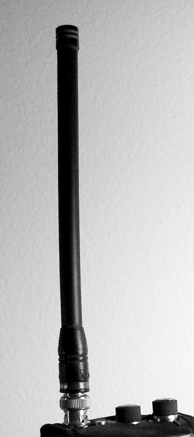
A handheld radio manufacturer selecting a stock antenna is not optimizing for radio performance first, and there is no point pretending otherwise. The list, in the order it actually gets weighted at OEM volume, runs: survive a meter-and-a-half drop onto concrete; flex without cracking when the radio rides in a pocket or a hip holster; look unmistakably like an antenna to a buyer who has never heard of a J-pole; cost under a couple of dollars in volume; and, somewhere after all of that, work adequately as a radiator. A short helix of springy wire — phosphor bronze or steel, sometimes copper-plated, wound tight and encapsulated in an injection-molded rubber or PVC sleeve — satisfies the first four criteria about as well as any physical object can. It survives being sat on, it looks correct, and it is nearly free. What it is not optimized for, at any point in that design process, is radiating efficiently, and every downstream complaint about handheld range traces back to that ordering.
4.5.2 The physics of a normal-mode helix
A helix operates in what Kraus’s classic treatment calls the normal mode when both its diameter and its winding pitch are much smaller than a wavelength — the regime every rubber duck lives in, since the entire structure is typically under a tenth of a wavelength long. In that regime the current flowing around each turn is close enough to in phase across the whole structure that the helix behaves, to the far field, like a single short linear radiator standing on end: an electrically short monopole, not a distributed traveling-wave structure. Figure: normal-mode helix current distribution shows why the current envelope along the unwound helix is a near-linear taper from a maximum at the feed to zero at the open tip, rather than the smooth half-cosine arc Vol 1 of the Single-Band Dipoles dive derives for a genuine half-wavelength element — an electrically short antenna only traverses a small fraction of a full sinusoidal cycle, and over that small fraction the cosine is indistinguishable from a straight line.

Winding the conductor into a helix does electrically lengthen it — the distributed inductance brings a physically short structure into resonance at a frequency a straight wire that length could not reach — but the winding buys that resonance at real cost. The helix’s own radiation resistance is intrinsically small, well under the roughly 36 Ω a full quarter-wave monopole presents, because a tightly wound short helix does very little genuinely radiating (antenna-mode) work relative to its closely-spaced, largely cancelling turns. With radiation resistance driven down toward a few ohms, any fixed resistive loss elsewhere in the structure — the wire’s own ohmic resistance, and critically its material — starts to dominate the efficiency calculation. Comparative measurements of otherwise identical normal-mode helices show a steel-spring conductor wasting roughly 3 dB relative to an equivalent copper-plated or brass one, purely from the steel’s higher loss competing against a radiation resistance too small to dominate it the way it would in a full-size element. Well-built, correctly matched copper-conductor helicals at 2 m have been independently measured anywhere from about 3 dB down to about 1 dB up relative to a full-size λ/4 whip — a genuinely wide spread tracking conductor quality and matching more than any single “helix efficiency” number could capture. A cheap OEM stock duck, built to a two-dollar cost target rather than a performance one, sits at the pessimistic end of that spread and often below it: a measured 5–15% radiation efficiency, and a real gain that can run negative before you ever reach the marketing department’s numbers.
4.5.3 Pattern distortion
The same shortness and the same body proximity Vol 1 already establishes as governing a handheld’s counterpoise also distort the shape of what a rubber duck does radiate, not just its magnitude. A full-size quarter-wave (or longer) monopole over any reasonable ground reference favors the horizon — the direction a repeater or a fellow operator actually occupies — with a null pointing straight up. A short helix, loaded and detuned by the nearby hand, head, and torso that constitute its only counterpoise, tends to push its pattern’s peak away from the horizon and toward higher elevation angles, sometimes well up toward 45°. The antenna is, in effect, least good exactly where it matters most operationally, and the deficit compounds with the raw efficiency loss from §5.2 rather than partially offsetting it.
4.6 The “high-gain rubber duck” lie
4.6.1 The actual physical bound, stated correctly
Any antenna that is omnidirectional in azimuth and vertically polarized — every entry in this volume, without exception — can only make gain one way: by taking radiated power that would otherwise go to high elevation angles and the zenith, and redirecting it down toward the horizon. That redirection is elevation-pattern compression, and the amount an antenna can achieve is set by how much physical and electrical aperture it has along its vertical axis — the same collinear-array logic that lets a 1–1.6 m, multi-section, phased base-station whip legitimately reach several decibels of real gain over a plain quarter-wave reference, purely by being several half-wavelengths of correctly phased aperture rather than one. The vehicle-mount mobile whips covered elsewhere in this dive earn their gain the same way: length, not cleverness.
This is a more precise, and more defensible, statement of the bound than “nothing this size can exceed roughly 2.15 dBi.” That looser framing is the source of an apparent contradiction worth naming directly: a stock 13 cm helical duck and a 38 cm Nagoya-class gain whip are not the same kind of object, and holding both to a flat “2.15 dBi ceiling” produces a contradiction the moment a real, physically-earned measurement of the longer whip nudges above that number. The aperture-based statement resolves it cleanly. A 13 cm helix, under a tenth of a wavelength on 2 m, has essentially no aperture to compress anything — its entire electrical length is a small fraction of the quarter-wave a plain reference whip already is, so it sits at or below the reference, and the “below” part can run deep (§5.2’s −5 to −10 dBi for a cheap example) once construction losses stack on the aperture shortfall. A 38 cm dual-band whip is not a stubby helix in the electrically-short sense at all — at 430 MHz, 38 cm is a substantial fraction of a wavelength, closer to a 5/8-wave element than a quarter-wave one, and a 5/8-wave monopole’s modest, well-documented few decibels over the plain quarter-wave/dipole reference is earned by genuine elevation-pattern compression from genuine extra length — the identical mechanism the base-station whips use, just a smaller dose. That an independently measured, real product can land at 2.7–3.1 dBi against a manufacturer’s claim of 2.15–3.0 dBi is therefore not a violation of any physical bound; it is exactly what a modestly-longer-than-quarter-wave radiator is supposed to do.
Figure: elevation pattern, same absolute dBi scale — stock duck vs. full-size λ/4 whip vs. J-pole puts three representative shapes on one absolute radial axis rather than three separately normalized ones, which is deliberate: normalizing each curve to its own peak, the way a shape-only comparison would, hides exactly the inconsistency §6.1 just resolved. On a shared scale, the J-pole’s and the full-size whip’s elevation lobes both peak near the horizon at roughly +2 and +1 dBi, consistent with §4 and §3; the stock duck’s lobe sits several decibels lower everywhere, its own peak pushed up toward 45° rather than the horizon per §5.3, and it never approaches — let alone exceeds — the other two curves at any angle. A fabricated “9 dBi duck” trace would have to dwarf both of the honest curves on this same plot, which is exactly why an absolute-scale figure is the right check to draw before printing a gain number: it either survives being drawn next to its competitors, or it doesn’t.

4.6.2 dBi, dBd, and which reference a figure actually used
Vol 1 of the Single-Band Dipoles dive fixed the conversion this whole hub relies on: 0 dBd is defined as a half-wave dipole’s own free-space directivity, 2.15 dBi, so dBi = dBd + 2.15. Vendor literature in the handheld-and-mobile-whip space is not reliably careful about which of the two it is quoting, and the gap that carelessness opens is large enough to manufacture an impressive-looking number out of an unimpressive antenna without anyone technically lying. A documented real example: the Diamond CP22E has been marketed at “6.5 dBd” — which, honestly converted, is 8.65 dBi — while independent NEC simulation of the same antenna shows closer to 5.1 dBi, a shortfall of roughly 3.5 dB after giving the marketing claim the benefit of the dBd-to-dBi conversion. Any gain figure in this space is close to meaningless without knowing which reference it is quoted against.
4.6.3 What reference ground plane, and whose body
A quarter-wave monopole’s textbook 5.15 dBi figure assumes an infinite, lossless ground plane — a fiction no handheld will ever see. The same element measured in free space, with no ground reference at all, reads closer to the plain dipole’s 2.15 dBi. Measured on an actual handheld radio, pressed against an actual operator’s actual body, it lands somewhere between those two idealized numbers and is shaped by exactly how much of that body is coupled in as counterpoise — precisely why Vol 1’s tiger-tail and grip-sensitivity discussion matters here too. This is the concrete reason independent test results for the “same” antenna scatter as widely as they do: a manufacturer’s anechoic-chamber, ideal-ground-plane number, an independent reviewer’s over-the-air comparison on a specific handheld, and a forum poster’s SWR-meter impression are three measurements of three different physical situations, and none is dishonest merely for disagreeing with the other two. The defensible summary, without false precision: a full-size quarter-wave-or-longer whip on a handheld runs close to unity gain — roughly 0 to +3 dBi as commonly measured, tracking the test fixture and the operator’s grip — and a stock helical duck sits several decibels below that, with the deficit tracking construction quality as much as length.
4.6.4 Why “9 dBi” and “12 dBi” claims fail on their own terms
An antenna’s directivity and its elevation beamwidth are linked by a standard approximation from Kraus’s own text: for an antenna with an omnidirectional azimuth pattern (a 360° horizontal beamwidth) and some elevation half-power beamwidth θ_E in degrees, directivity in dBi runs close to 10·log₁₀(41253 / (360 × θ_E)), which reduces to roughly 10·log₁₀(114.6 / θ_E). Solving that relation backward for the beamwidth a claimed gain figure would require is illuminating. A genuine 9 dBi omnidirectional antenna needs an elevation beamwidth compressed to roughly 14–15°; a 6 dBi antenna needs roughly 29°. Compressing an elevation pattern to a beamwidth that tight is exactly the collinear-array problem §6.1 already described — it takes several wavelengths of correctly phased vertical aperture, the same mechanism a genuine gain-whip base antenna uses over a meter-plus of physical length. A rubber duck’s entire structure is under a tenth of a wavelength. There is no aperture in it to compress anything, let alone to the 14° beamwidth a 9 dBi claim implicitly demands, and no amount of clever winding changes that arithmetic. What is actually being measured, on the rare occasion an independent reviewer bothers to measure a “high-gain” duck properly, typically runs from about −2 to +1 dBi — worse, not better, than a genuine full-size Nagoya-class whip costing the same or less. Don’t buy antennas marketed on a dBi figure disconnected from a stated physical length and reference condition; buy the physical length instead, and let Vol 5’s buy survey tell you which specific products currently deliver it.
4.7 Telescoping whips for SDR receive
4.7.1 The RTL-SDR Blog kit
The default cheap, general-purpose receive antenna for an RTL-SDR, HackRF, or similar wideband SDR is the RTL-SDR Blog Multipurpose Dipole Antenna Kit — a genuine center-fed dipole, not a monopole riding on a ground plane. The kit ships a center base (60 cm of built-in RG-174, a 1/4-inch camera-screw mount), two longer telescoping elements running 23 cm collapsed to 1 m extended, two shorter elements running 5–13 cm, a 3 m RG-174 extension, a flexible tripod mount, and a suction-cup mount. The camera thread is the same standard a magnetic camera mount uses, which is how many users add a magnetic base of their own for a car roof; the kit as sold does not include one.
Figure: telescoping-dipole element length vs. frequency plots the quarter-wave length L = 7500/f (centimeters, MHz) against the two element pairs’ physical ranges. The long pair, 23–100 cm per side, covers a quarter-wave resonance from roughly 75 MHz (low-VHF/high-HF, where 100 cm is exactly a quarter wave) down through the FM broadcast band (100 MHz, 75 cm) and the 2 m amateur band (146 MHz, about 51 cm). The short pair, 5–13 cm per side, covers the top end from roughly 577 MHz (13 cm) up past 1 GHz; 70 cm at 446 MHz wants about 17 cm per side, which is a few centimeters beyond the short pair’s maximum reach — workably electrically short for receive, per §7.2, but worth knowing rather than assuming the kit reaches every UHF amateur band at full resonant length.

4.7.2 Why receive relaxes the efficiency constraint — the actual mechanism
The claim that antenna loss “doesn’t matter as much” for SDR receive is true, but it is worth being precise about why, because the same claim breaks down hard once the underlying assumption stops holding. A receiving system’s usable sensitivity is set by whichever noise source is larger where signal and noise are compared: the noise the receiver’s own front end contributes (its noise figure), or the external RF noise the antenna delivers along with the desired signal — atmospheric, galactic, and man-made noise, characterized systematically in ITU-R P.372. Below roughly 1 GHz, and dramatically so through HF and low VHF, the external noise floor commonly runs tens of decibels above a typical receiver’s own thermal floor. In that regime an antenna’s resistive loss attenuates the desired signal and the external noise it is also picking up by essentially the same amount — both pass through the same lossy front end — so the ratio between them, which is what determines whether you can copy the signal, barely moves even as the antenna throws away real absolute power. A lossy, electrically short receive antenna in a noise-floor-dominated band is not delivering full sensitivity, but it does not need to: there was surplus margin to spend.
That argument has a boundary, and past it the antenna’s loss costs you signal one-for-one exactly as it would for transmit. The external noise floor drops steeply with frequency, and above roughly 1–2 GHz — well into where GPS, ADS-B, and cellular live — galactic and atmospheric noise typically falls below a competent receiver’s own noise figure, so every decibel the antenna loses from that point up is a decibel of real sensitivity gone. The same reversal happens situationally at lower frequencies too: a genuinely quiet rural site with low man-made noise, or any narrowband weak-signal application — satellite downlinks, EME, precision GPS timing — pushes the crossover down and makes antenna efficiency matter again. A casual FM-broadcast or trunking scan from a noisy apartment is exactly the situation the “receive relaxes the constraint” argument was built for; a weak-signal EME attempt or an ADS-B feeder chasing maximum range from a quiet rooftop is exactly where it stops applying.
Wideband coverage across a broad span rather than one tuned resonance is the discone family’s job, and dedicated low-noise active receive loops for space-restricted HF/low-VHF work are covered in the receive-only loops dive — both genuinely different design problems from the simple resonant telescoping dipole this section covers, and neither duplicated here.
4.8 Best-case, worst-case, and power handling
4.8.1 Best case
This family is at its best exactly where its members were designed to operate. A roll-up J-pole or a genuine Ed Fong DBJ-2, hoisted up a tree or a push-up mast, is the field-day and SOTA/POTA default for a reason: no radial system to plan, and — per §4 — a genuine, measured multi-decibel advantage over running the same handheld on a bare antenna at UHF. A $25–45 upgrade from a stock rubber duck to any genuine full-size whip (Nagoya-class or better) is close to the best return-on-investment upgrade available anywhere in a handheld radio system: §6 shows the stock duck is giving away several real decibels to construction economy, and a longer element buys most of that back cheaply. Cheap, general-purpose SDR receive scanning across a broad span, where §7.2’s noise-floor argument holds, is the other clear win.
4.8.2 Worst case
HF simply is not this family’s problem — every antenna here is a VHF/UHF structure by design, and none of the length or matching tricks in this volume scale down to 80 or 40 m without becoming a different antenna (that territory belongs to Vol 1 of this dive and to the random-wire/end-fed dive). Indoors, any antenna here gives up the open-air deployment its pattern assumes and picks up local RFI and near-field detuning instead. High-power transmission is a poor fit across the board — §8.3 explains why. And direction-finding is a non-starter: every antenna covered here is deliberately omnidirectional in azimuth, exactly the property that makes it useless for finding a null.
4.8.3 Power handling: two distinct failure modes, correctly scoped to this family
The antennas in this volume are not the loaded HF whips (ham-sticks, MP-1-style coils) where a large loading inductor is the obvious power bottleneck — that belongs to a different part of this dive. What actually limits power here falls into two distinct mechanisms.
The first is ferrite-core common-mode choke saturation. Every properly built antenna in this family — the roll-up J-pole, the DBJ products — carries a ferrite-bead or toroidal choke on its coax feed, per §2.2’s balance argument, and that choke is a real magnetic core at a real flux density. Drive it at high power, especially under an imperfect match where reflected power raises the current it sees, and the core can saturate: inductance collapses, common-mode loss rises, the choke heats, and the ferrite can crack. The fix is standard ferrite-choke engineering — more beads, a larger core, or a better match — but it is a genuine failure mode distinct from simple resistive heating.
The second is conductor and joint heating. Ed Fong’s own design notes are directly on point: the DBJ-1/DBJ-2’s RG-174 decoupling stub and lead-in limit the antenna to under 60 W precisely because RG-174 is thin coax with a modest power rating, and substituting a heavier cable (RG-213, RG-8, RG-58) requires recalculating the decoupling stub’s length for the new velocity factor rather than assuming the dimensions carry over. Separately, a cold-soldered or corroded joint at the shorted stub bar or the feed tap is a classic RF construction failure: a poor mechanical connection concentrates I²R heating exactly at the point carrying the most current, and fails there first.
Rubber ducks rarely fail from over-driving in practice, since a handheld transmitter tops out around 5–8 W — but the mechanism is worth stating, because it is the same physics inverted. §5.2 established that a stock duck’s poor efficiency comes from resistive loss dominating a tiny radiation resistance; feed that same lossy structure serious power and nearly all of it turns to heat in the winding and surrounding rubber rather than radiating, which is exactly why over-driven rubber ducks are a documented way to melt the jacket. The antenna inefficient as a radiator is, by the same token, an efficient heater.
4.9 Where this volume hands off
This volume worked through the electrical theory of the handheld and deploy-and-go VHF/UHF family: why an end-fed half-wave’s feedpoint impedance runs into the thousands of ohms and how a shorted quarter-wave stub transforms it back to 50 Ω, where the feed tap lands and why no one publishes an exact number for it, the real (if modest) radiation the stub itself contributes, the honest sizing of the Slim Jim’s advantage over a plain J-pole, and — verified against Ed Fong’s own primary-source papers — the actual coaxial-decoupling-stub mechanism behind the DBJ-1 and DBJ-2’s dual-band operation, which is not the harmonic coincidence it is sometimes described as. It worked through the normal-mode-helix physics that makes a rubber duck a rubber duck, and it built the gain argument of §6 to survive its own numbers: the correct bound on an omnidirectional vertical’s gain is elevation-pattern compression scaling with electrical aperture, not a flat dBi ceiling — the correction that lets a genuinely poor stock duck and a genuinely modest gain-whip both be telling the truth about their very different measured numbers. It closed with the real reason SDR receive tolerates a lossy telescoping whip — external noise floor dominance below roughly 1 GHz — and where that tolerance runs out.
What it did not do is build anything. Vol 5 picks up with the hands-on side: a step-by-step DIY build of the canonical roll-up 2 m J-pole, a NanoVNA-based trim-and-sweep procedure for finding your own feed tap rather than trusting a published one, and the ranked commercial-buy survey — Nagoya, Diamond, Smiley, the genuine Ed Fong DBJ-1/DBJ-2 products, and the RTL-SDR Blog kit — with current pricing and an explicit list of what to avoid, built on the physical-bound argument this volume just established.
4.10 Resources
- ARRL Antenna Book (25th+ ed.), VHF/UHF antennas chapter — the canonical treatment of the J-pole and Slim Jim family.
- Edison Fong, WB6IQN, “The DBJ-1: A VHF-UHF Dual-Band J-Pole,” QST, February 2003, pp. 38–40 — the primary source for the coaxial-decoupling-stub mechanism and the measured performance tables cited throughout §4.
- Edison Fong, WB6IQN, “The DBJ-2: A Portable VHF-UHF Roll-up J-pole Antenna” (2005) — the roll-up portable version, confirming the identical decoupling-stub principle.
- L. B. Cebik, W4RNL, “What is a Slim Jim?” and the associated J-Pole series (antenna2.github.io/cebik) — the NEC-modeled analysis of stub radiation, pattern asymmetry, and the honest Slim-Jim-vs-J-pole gain comparison.
- Kraus, Antennas — the normal-mode helix condition, the omnidirectional-directivity-vs-beamwidth approximation used in §6.4, and the general short-antenna current-distribution treatment.
- ITU-R Recommendation P.372, Radio Noise — the standard reference for atmospheric, galactic, and man-made noise floors underlying the SDR-receive noise-floor argument in §7.2.
- RTL-SDR Blog product documentation — the Multipurpose Dipole Antenna Kit’s specifications.
- Vol 1 of this dive — the handheld counterpoise problem and the Chu-Harrington small-antenna limit this volume applies throughout.
- Vol 1 and Vol 4 of the Single-Band Dipoles dive — the standing-wave/current-distribution and folded-dipole derivations this volume cites rather than repeats.
Comments (0)