Random Wire & End-Fed Antennas · Volume 1
Why End-Feeding Works At All
The standing wave and the two places you can feed it, why the end impedance is high and why it is not a constant, what 'no radials' actually costs, and the counterpoise as a deliberate return path
1.1 About this volume
The end-fed wire is the most-deployed HF antenna of the last fifteen years, and it earned that position honestly. A single length of wire, one support at the far end, a small ferrite transformer at the near end, and one coaxial run back to the rig — no centre insulator to hoist, no radial field to lay, no balanced feeder to keep clear of metal. It goes up in ninety seconds from a backpack and it fits a lot where nothing else will. The physics that makes it work is genuinely elegant, and it is also the physics that makes it the most misexplained antenna in amateur radio.
This volume deals with the foundation: why you can feed a half-wave at its end at all, what impedance you actually find there, and what happens to the return current when you build an antenna with only one half. Everything else in this dive stands on those three questions. The resonant end-fed half-wave and its harmonic bands are Vol 2; the non-resonant random wire, long wire and their geometric variants are Vol 3; the feedpoint in practice — transformer selection against a measured impedance, counterpoise length, and the common-mode current that makes the feedline a second antenna — is Vol 4; the build, the bench measurement and the commercial survey are Vol 5.
Two of this volume’s conclusions run against the received wisdom, so they are worth stating plainly at the top rather than burying them in a subsection.
The first is that 2450 Ω is a design convention, not a property of half-wave wires. It is repeated so uniformly across kit instructions, club talks and vendor pages that it reads like a measured constant of nature. It is not. It is what you get when you multiply 50 Ω by 49, and 49 is the square of the 7:1 turns ratio that happens to be convenient to wind. The impedance at the end of a real wire depends on the conductor’s diameter, its height, what is near it, how much loss the system carries, and — most sharply of all — exactly where the transformer effectively connects. §3 derives how steeply it varies and shows why this is the least reproducible number on the antenna.
The second is that a counterpoise does not add gain. The figures often quoted — “3–5 dB better on receive” — conflate two different quantities. A passive antenna is reciprocal: its gain is identical on transmit and receive, and no counterpoise changes that. What a counterpoise changes is which conductor carries the return current, and therefore the signal-to-noise ratio, which is a different thing and genuinely can differ between transmit and receive. §5 and §6 make that distinction carefully, because getting it wrong is how a real and useful piece of advice ends up resting on an impossible claim.
1.2 The standing wave, and the two places you can feed it
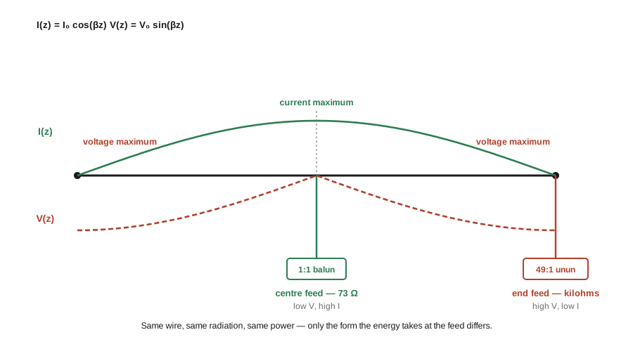
A conductor a half-wavelength long, driven at its resonant frequency, carries a standing wave whose shape is fixed by what happens at its two open ends. Current cannot flow past a wire tip into air, so the current must be zero there. The only sinusoidal distribution that is zero at both ends of a half-wave-long element is a single half-cycle of a cosine measured from the centre. Writing z for position along the wire from the centre and β = 2π/λ,
I(z) = I₀ · cos(βz) and V(z) = V₀ · sin(βz)
over −λ/4 ≤ z ≤ +λ/4. Current peaks at the centre and vanishes at the tips; voltage does the opposite. They are spatial quadrature partners, which is the same relationship an open-circuited quarter-wave transmission-line stub presents at its driven end — a dipole is, electrically, a pair of such stubs folded open until they radiate.
That single picture contains the whole end-fed idea. The radiating structure does not care where you attach the feedline. The current distribution above is a property of the resonant wire, not of the feed arrangement; establish that standing wave and the wire radiates the same pattern with the same efficiency regardless of which point you chose to inject power. What changes with the feed point is only the ratio of voltage to current you must supply — and therefore the impedance your transmitter sees.
Feed at the centre, where the current is maximum and the voltage near zero, and you are asked for a lot of current at low voltage: about 73 Ω for a resonant half-wave in free space, close enough to 50 Ω coax that a 1:1 current balun finishes the job. That is a dipole, and it is the subject of the single-band dipole dive.
Feed at a tip, where the voltage is maximum and the current small, and you are asked for the reciprocal bargain: high voltage, low current, an impedance of kilohms. That is an end-fed wire, and it needs a step-down transformer of roughly 50:1 to present something a transmitter will accept.
The power delivered is the same either way. The radiation is the same. Only the form the energy takes at the feedpoint differs — and with it, the hardware. A centre feed sits at a current maximum, so its enemy is resistance: a corroded joint or an undersized lug there burns real power as I²R heat at the exact point the current is largest. An end feed sits at a voltage maximum, so its enemy is dielectric breakdown. At the legal limit the standing-wave voltage at the tip of a thin wire runs into the kilovolts, which is why an end-fed transformer’s compensation capacitor is specified in kilovolts rather than being whatever ceramic disc is in the junk box, and why the insulator at the far end of an end-fed wire is a high-voltage RF component rather than a piece of string-tie hardware.
This is also the honest answer to the most common objection to end-fed antennas — that they are somehow “inefficient” because they are fed at a high-impedance point. They are not. A high feedpoint impedance costs nothing by itself; it is a matching problem, not a loss mechanism. The losses in an end-fed system are real and can be substantial, but they live in the transformer rather than in the geometry, and they are the subject of Vol 4 and Vol 5.
1.3 Why the end impedance is high — and why it is not a constant
Now the number itself. If the current at position z is I₀ cos(βz), and the radiated power P = ½|I|²R is a property of the whole antenna rather than of the point you chose to feed, then the resistance seen at that point must rise exactly as fast as the current falls:
R(z) = R_centre / cos²(βz)
with R_centre ≈ 73 Ω. That is the entire derivation, and it is worth sitting with, because the 1/cos² is brutal. The figure below plots it against distance from the wire tip, expressed as a percentage of the antenna’s total length.
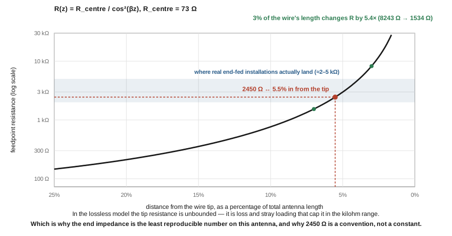
Read the numbers off it:
Table 1 — Read the numbers off it
| Distance from the tip (% of total length) | R |
|---|---|
| 10 % | 764 Ω |
| 7 % | 1 534 Ω |
| 5.5 % | 2 470 Ω |
| 5 % | 2 983 Ω |
| 3 % | 8 243 Ω |
| 2 % | 18 515 Ω |
| 1 % | 73 989 Ω |
Between 3 % and 7 % of the wire’s length — on a 40 m half-wave, a span of about 85 cm — the resistance changes by a factor of 5.4. In the lossless model it does not converge to any value at all: as z → λ/4, cos(βz) → 0 and R → ∞. There is no such thing as “the impedance at the end of a half-wave.” The tip resistance is unbounded, and every finite number ever quoted for it is a statement about something other than the ideal wire.
What caps it in reality is a combination of effects, all installation-dependent:
- Loss. Conductor resistance, dielectric loss in insulators and nearby objects, and ground absorption all put a floor under the current at the tip, and therefore a ceiling on the resistance.
- Stray capacitance at the transformer. This one is larger than most builders expect. AF7NX measured the effective capacitance at his transformer’s output and found it rose to about 6.0 pF simply from mounting the transformer in its box and bringing the output through an antenna connector — against roughly 1.6–2.7 pF for the bare winding. At a source impedance of 2450 Ω, he notes, a few picofarads already matters by 30 MHz. The box is part of the antenna.
- Height and surroundings. Ground proximity and nearby conductors load the high-voltage end, which is precisely the part of the antenna most sensitive to being loaded.
- The counterpoise. Adding a deliberate return path changes the impedance presented at the feed, which is one reason §6’s counterpoise is a tuning element and not merely a safety measure.
1.3.1 Resistance is only half of the feedpoint
Everything above is the resistive part, and it is worth being explicit that the model deliberately stops there. A real feedpoint is complex, Z = R + jX, and the reactance is not a small correction near the end of a wire — it swings at least as violently as the resistance does, and for the same reason. The wire is exactly resonant (X = 0) at one frequency; a few percent either side of it the element looks inductive above resonance and capacitive below, and at the high-impedance end that reactance is scaled up by the same standing-wave transformation that scales up the resistance.
This matters practically because a transformer transforms the whole complex impedance, not just its resistive part. A 49:1 unun presented with 2450 + j1000 Ω delivers 50 + j20.4 Ω to the rig — the reactance divides by 49 exactly as the resistance does. That is genuinely helpful: the same ratio that tames a kilohm-scale resistance also tames a kilohm-scale reactance, and it is part of why these antennas behave as well as they do across four bands. But it also sets the limit. A fixed-ratio transformer cannot cancel reactance, only scale it, so an antenna that is badly off resonance on some band arrives at the rig still off resonance, just with smaller numbers.
Two things follow that are easy to get backwards. First, the compensation capacitor found across the primary of most 49:1 transformers is not there to cancel the antenna’s reactance; it compensates the transformer’s own high-frequency behaviour, and AF7NX’s measurements show it is a poor fit for winding styles that already achieve low leakage inductance. Second, when a builder cannot get a particular band to behave, the fix is nearly always on the wire — trimming length, or a small compensation coil placed where the current is significant on the troublesome band — rather than on the transformer ratio. The ratio addresses the resistance; the wire addresses the resonance.
So where does 2450 Ω come from? Read the table again: 2450 Ω is what the ideal model gives about 5.5 % of the antenna’s length in from the tip — on a 40 m half-wave, roughly 1.2 m. That is not a claim that transformers are literally connected a metre from the end. It is a way of seeing how far from the true tip you must be before the ideal curve falls to the canonical figure, and therefore how modest an amount of real-world loading is needed to land there.
The honest statement is the reverse of the usual one. We do not use a 49:1 transformer because half-wave wires present 2450 Ω. We quote 2450 Ω because the industry settled on a 49:1 transformer, and 49 × 50 = 2450. The number is the ratio’s implication, not a measurement.
That said, the choice is not arbitrary, and it would be an over-correction to say so. AF7NX modelled a 41 m end-fed wire in NEC across a range of drive impedances and counterpoise lengths, and concluded that “‘Best’ results are with 2450Ω drive impedance and the 3.3m counterpoise, so it is not surprising that 49:1 transformers are the common choice.” The convention is a well-chosen compromise for a complete system — wire plus counterpoise plus a typical installation — even though it is not a property of the wire alone.
The spread around it is wide, and any volume that quotes a single figure is misleading its reader:
- The ARRL’s own kit page describes the antenna as having “a very high impedance of around 2,500 Ohms” — the convention, stated as such.
- A practitioner running an 80 m end-fed found he needed 20 secondary turns rather than the usual 14, “suggesting that the impedance is nearer 5000 ohms than 2500.”
- On the upper harmonic bands the resistance goes the other way: for an antenna resonant at 80 m, the wire impedance on 10 m can fall to 600–1000 Ω, and the match there is rescued not by the 49:1 ratio being correct but by parallel resonance between the wire’s reactance and the transformer’s secondary capacitance.
- A representative per-band set — 2450 Ω at 7 MHz, 1500 Ω at 14 MHz, 5000 Ω at 18 MHz — is used as an illustration both in Vol 2 and in the antenna tuners dive. ⚠ No source was found for it as a measurement of any specific antenna, so it stands as a picture of the spread rather than as data. Even taken that way, a spread is a far more honest picture of a multi-band end-fed than any single number is.
The practical consequence is the one to carry forward: an end-fed antenna is a system whose feedpoint impedance you should expect to measure rather than assume, and whose SWR is expected to differ band to band. A builder who believes 2450 Ω is a constant will conclude that a wire showing 3:1 on 20 m is broken. It is not broken; it is behaving exactly as the 1/cos² curve and a real environment predict.
1.4 The 49:1 ratio, and what it is actually claiming
A transformer with N times as many secondary turns as primary turns transforms impedance by N². Seven turns to one gives forty-nine to one; into 50 Ω that is 2450 Ω. The arithmetic is unremarkable, and it deserves to be stated cleanly because this corner of the hobby has accumulated a surprising amount of muddle around it — including, in the previous edition of this chapter, an assertion that the turns arithmetic needed correcting for “leakage and magnetic coupling.” It does not. 14² / 2² = 49, exactly, with no correction term, and there is no such mechanism. That claim has been removed.
What deserves more attention is what the ratio is claiming. A 49:1 transformer does not make an antenna present 2450 Ω. It asserts that if the antenna presents 2450 Ω, the transmitter will see 50 Ω. Feed it 5000 Ω and the transmitter sees about 102 Ω — a little over 2:1. Feed it 1000 Ω and the transmitter sees roughly 20 Ω, about 2.4:1. The transformer is a fixed ratio applied to a variable load, which is precisely why a multi-band end-fed shows a different SWR on every band even when everything is working correctly.
Two consequences follow, both developed later in the dive.
The first is that the turns ratio is a choice about impedance, while the turn count is a choice about bandwidth and core. A 2:14 winding, a 3:21 winding and a 5:35 winding are all 7:1, all 49:1 in impedance, and they behave very differently: more primary turns means more magnetising inductance, less flux in the core and lower loss, at the cost of more winding capacitance and a worse high-frequency limit. VK3IL states the design rule that actually drives the choice — “as a rule of thumb you want at least 200 ohms on the transformer primary winding to avoid the transformer impacting the impedance seen by the transmitter too much” — which is why the low bands want 3:21 or 3:24 and the high bands want 2:14 or 2:16. The measured evidence behind this, and the reason it matters far more than core size does, is in Vol 4.
The second is that a 64:1 (8:1 turns) transformer is not a mistake or a marketing variant; it is the same design aimed at 3200 Ω instead of 2450 Ω, which is a defensible read of a longer or higher wire. 64 × 50 = 3200 — again, the ratio defines the target, and the target needs no further explanation in terms of wire length or Q.
The transformer’s own construction — winding topology, ferrite mix, why the mix-43 versus mix-31 question has a frequency-dependent answer, and the compensation capacitor — belongs to the BALUNs and UNUNs dive, which treats it at transformer-designer depth and which this dive leans on rather than duplicating.
1.5 What “no radials” actually means
Here is the claim that sells end-fed antennas, and it is half true in a way worth taking apart carefully.
A centre-fed dipole is electrically self-contained. The two quarter-wave halves are each other’s return path: current flowing out into one arm is exactly balanced by current flowing out into the other, and the balun’s only job is to stop that balanced pair becoming unbalanced on the way down the feedline. Nothing outside the antenna is required to complete the circuit.
An end-fed wire has no second half. Current flowing into the wire has to come from somewhere, and it must return to the source. The transformer’s ground terminal is one side of a circuit, and something has to be connected to it. The question is never whether there is a return path — there always is — but which conductor provides it.
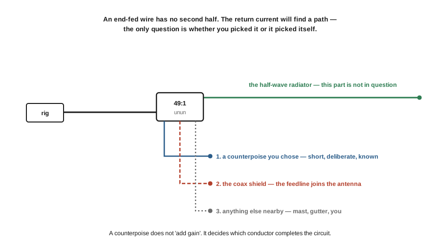
The candidates, in the order they tend to volunteer:
- A counterpoise you deliberately attached — short, known, under your control.
- The coax shield. If nothing else is connected, the outside of the braid becomes the return conductor. The feedline stops being a feedline and becomes part of the antenna.
- Everything else — the mast, a gutter, the station ground, the operator.
“No radials required” is therefore true in a narrow and useful sense and false in a broad one. True: an end-fed half-wave genuinely does not need the radial field that a quarter-wave ground-mounted vertical needs, because the radiating element is a complete half-wave that establishes its own standing wave; the return path handles a small current, not the antenna’s full current. That is a real and substantial advantage, and it is why an end-fed goes up in a fraction of the time a vertical takes. False: the antenna is not exempt from needing a return path at all. It has one whether or not you provided it.
What does it cost when the coax shield takes the job by default? Not gain — and this is where the conventional advice goes wrong. A passive antenna is reciprocal: its gain is identical on transmit and on receive. It is not physically possible for a structural change to buy 3–5 dB on receive and only 0.5–2 dB on transmit, and a figure pair of that shape is a reliable sign that two different quantities have been conflated. What actually differs between the two directions is signal-to-noise ratio, and the mechanism is specific:
- On receive, a feedline whose shield carries antenna current is itself an antenna — one that runs from the roof, down the side of the house, past the consumer electronics and into the shack, which is an almost optimal geometry for collecting locally generated noise. The wanted signal is unchanged; the noise floor rises. The operator experiences this as “the antenna is deaf,” though the antenna’s gain has not moved.
- On transmit, the same current on the outside of the braid brings RF back into the shack: hot microphones, USB dropouts, RF bites on a metal chassis, distorted audio reports. The radiated power is essentially unchanged; what changes is where some of it ends up.
So the correct claim is not that a counterpoise makes the antenna better, but that it makes the antenna predictable, and stops the feedline being a second, uncontrolled radiator. That is a more modest claim than the one usually made, and it is the one that survives contact with reciprocity.
1.6 The counterpoise as a deliberate return path
Given the above, the counterpoise’s job is easy to state: it is a conductor attached to the transformer’s ground side so that the return current has an obvious, short, low-impedance path that is not the coax.
The single most-mistuned variable in end-fed practice is its length, and the conventional instinct — “a counterpoise is a radial, so make it a quarter-wave” — is wrong here. A quarter-wave counterpoise is a resonant element, and hanging a resonant element off the transformer’s ground terminal makes it part of the antenna, shifting the tuning band by band and defeating the multi-band behaviour that is the whole point. What is wanted instead is a short, deliberately non-resonant wire: enough to be a definite return path, not enough to be a radiator.
The working figure is 5–10 % of the radiator’s length, and it now has modelled support rather than only folklore. AF7NX’s NEC study drove a 41 m end-fed wire at a range of impedances with counterpoises of 3 % (1.23 m) and 8 % (3.28 m), and reported:
- “‘Best’ results are with 2450Ω drive impedance and the 3.3m counterpoise” — 3.28 m on 41 m is 8 %, squarely inside the conventional 5–10 % range.
- “With a very short counterpoise it is difficult to resonate the fundamental with any drive impedance” — the 3 % case is genuinely too short, so the lower bound is real rather than merely cautious.
- “Increasing the drive impedance tends to move the resonances to slightly higher frequencies” — confirming that the counterpoise and the transformer ratio interact, and that the two should be chosen together.
- Adding another 2 m to the counterpoise changed the resonant frequencies very little — “much less than adding that length to the main wire would accomplish.” This is the useful practical result: once the counterpoise is long enough to do its job, making it longer is not a tuning control. Trim the radiator, not the counterpoise.
For a 40 m end-fed half-wave of about 20 m, that puts the counterpoise in the range of roughly 1–2 m. For an 80 m wire of about 40 m, 2–4 m.
Two refinements matter enough to state here, though both are developed properly in Vol 4.
The coax shield is already a counterpoise, whether you like it or not. VK3IL makes the point directly, answering a builder who found that adding a short counterpoise changed nothing measurable: “with this type of matching unit, the coax shield essentially plays the role of a counterpoise, so adding a separate counterpoise is unlikely to make much difference.” This is not an argument against counterpoises — it is an argument for understanding what you already have. If the shield is doing the job, the antenna works; it works with the feedline as part of the antenna, with the noise and RF-in-the-shack consequences of §5. Adding a counterpoise without also decoupling the shield often changes very little, because you have given the current a second path rather than moving it off the first.
Which is why the counterpoise and the common-mode choke are one design decision, not two. The counterpoise offers the return current a path; the choke raises the impedance of the path you do not want. Neither alone reliably does the job. A choke at the transformer presents a high impedance to current trying to flow onto the braid’s outside, and the counterpoise gives that current somewhere better to go. The subtlety — that a high choking impedance can make matters worse if it is reactive rather than resistive, because it can resonate with the common-mode path — is established in the BALUNs and UNUNs dive and applied to end-fed systems in Vol 4.
A last note on expectations. None of this makes the counterpoise a performance upgrade in the sense of a gain figure. It is a control measure. The antenna will very likely “work” without one — a great many do — and the reader who adds one should expect the improvement to show up as a quieter receive noise floor and a station that stops misbehaving at full power, not as more S-units on transmit.
1.7 Where this volume hands off
The foundation is in place: a resonant wire carries a fixed current distribution; feeding it at a voltage maximum rather than a current maximum changes the impedance and nothing else about the radiation; that impedance is high, unbounded in the ideal case, and in practice set by loss and loading rather than by any constant; a 49:1 transformer is a fixed ratio aimed at a conventional target; and an end-fed wire always has a return path, which the builder should choose deliberately.
From here:
- Vol 2 — The resonant end-fed half-wave takes the λ/2 cut and the harmonic bands: which harmonics land inside amateur allocations and which do not, why the same wire shows a different SWR on each band (§3 and §4 have already supplied the reason), and how height and surroundings move the resonances.
- Vol 3 — Non-resonant wires covers the random wire, the long wire, the inverted-L and the sloper — why “random” is not arbitrary, which lengths to avoid and why, and the 9:1-plus-tuner system, which is a different design philosophy rather than a cheaper version of the same one.
- Vol 4 — Feed, counterpoise and the ground question is where the feedpoint becomes practical: selecting a transformer against a measured impedance rather than an assumed one, counterpoise length in the field, the loss mechanism that actually limits these transformers, and common-mode current as the second device in the system.
- Vol 5 — DIY build, measurement and buys builds a 40 ft end-fed half-wave, cuts and trims it with a VNA, and surveys what is worth buying.
Two items are owed against this volume and are recorded rather than quietly skipped. A photographic lead image is wanted — the dive’s existing winding diagram belongs to Vol 4, where the transformer is the subject. And per-band feedpoint measurements that would replace §3’s modelled spread with measured values on a specific antenna are a bench task rather than a literature one; the NanoVNA dive has the method.
1.8 Resources
- Fair-Rite Products — material datasheets for mixes 43, 31 and 52, and the individual toroid product pages. The primary source for anything about core material; vendor and forum restatements of these figures are frequently wrong.
- AF7NX, Engineering the EFHW 49:1 Transformer and Antenna (Squash Practice, 2021) — the NEC drive-impedance and counterpoise study quoted in §3 and §6, the stray-capacitance measurements, and a calorimetric loss measurement at real power. The most careful single treatment of this antenna’s feedpoint the author found.
- AF7NX, Performance of 49:1 Ferrite Core Transformers (Squash Practice, 2021) — NanoVNA-based transmission-loss measurements across core sizes and turns ratios; the basis for the turns-versus-loss argument previewed in §4 and developed in Vol 4.
- VK3IL, EFHW matching unit — the 200 Ω primary-reactance design rule, and the observation about the coax shield already acting as a counterpoise. The comment thread is unusually good.
- ARRL / HF Kits End-Fed Half-Wave Antenna Kit documentation — the canonical 2:14-on-FT240-43 build, and a clear statement of the 2500 Ω convention.
- Single-band dipoles, Vol 1 — the centre-fed half-wave, the same standing wave read from the other end.
- BALUNs and UNUNs, Vol 4 — transformer ratios in practice, including the 49:1 winding this volume treats as a black box.
- Antenna tuners, Vol 1 — the per-band feedpoint impedance set quoted in §3.
Comments (0)