Random Wire & End-Fed Antennas · Volume 5
DIY Build, Measurement and Buys
The winding the previous edition got wrong, a 40 metre end-fed built and trimmed with a VNA, why the published power ceiling is optimistic by a factor of 2.25, rating by duty cycle and SWR the way the trade does, what Part 97 actually limits, and a dated commercial survey
5.1 About this volume
This is the last volume, and it is where the dive stops deriving and starts building. Vol 1 gave the standing wave and the unbounded end impedance, Vol 2 the harmonic series and the height argument, Vol 3 the non-resonant wires and the length audit, and Vol 4 the measured feedpoint, the transformer’s real loss and the two conductors that carry the return current. What remains is a bill of materials, a procedure, a set of acceptance criteria, an honest account of how much power the thing will take, and a survey of what is worth buying instead.
It is also the volume with the most corrections in it, because a build section is where a wrong number becomes a wasted afternoon. Five things drive it.
The previous edition’s winding instructions build the wrong transformer. §2 is the correction and it is the most consequential single item in this dive. The chapter tells you to twist three wires trifilar, wind seven turns, and join them end to end. That is a 3:1 turns ratio — a 9:1 transformer. Built exactly as written it presents about 450 Ω where the antenna wants 2450 Ω, and the builder gets a poor match on every band and no way to diagnose it from the text.
The only published power analysis for these transformers uses the wrong Curie temperature. §5 works it through: it assumes 230 °C for mix 43 where Fair-Rite specifies greater than 130 °C on the very product page the analysis cites, so the allowable temperature rise is 80 °C rather than 180 °C and every published figure is optimistic by a factor of 2.25. Continuous capability drops from 23.1 W to 10.3 W; compressed-SSB capability from 231 W to 103 W.
Saturation is the wrong failure mode, and this dive has now found it described that way five times. §5 states the correction once, properly. The previous edition also claimed that severe saturation can “melt the toroid’s plastic casing or the magnetic-coupling wax” — a ferrite toroid has neither.
Power is not one number, and the trade already knows it. §6 uses two vendors’ own published ratings: MyAntennas rates a single transformer at 1 kW ICAS, 250 W digital, 100 W continuous — a ten-to-one spread on one part — and Palomar publishes an explicit SWR derating rule, “divide the rating shown in the table below by (square root of swr)”, which the section computes out.
And the harmonic section’s regulatory framing is backwards. §7: §97.307(d) limits the transmitter’s spurious output, not what the antenna radiates. An end-fed cannot put a compliant rig out of compliance. The clause that actually bites is (c).
5.2 The winding the previous edition described is not a 49:1
The previous edition’s construction section reads:
Cut 3 lengths of #14 enamel wire, each ~1 m long. Twist the three wires together at 4 turns per inch […] Wind the trifilar bundle through the FT240-43 toroid: 7 turns […] Connect A’ (the other end of wire A) to B (the start of wire B). Connect B’ to C.
Count the turns that result. Three wires of seven turns each, joined end to end, form one continuous winding of 21 turns with taps every seven. Feed it across one seven-turn section and take the output across all twenty-one, and the turns ratio is 21/7 = 3, so the impedance ratio is 3² = 9.
That is a 9:1 transformer. It is, in fact, exactly the trifilar 9:1 the same chapter describes correctly two sections earlier for random wires — the instructions have been pasted into the end-fed half-wave build. A builder following them lands about 450 Ω on the antenna side where a half-wave end wants something in the low kilohms, and gets a mismatch of roughly five to one that no amount of wire trimming will fix. The connection list that follows is also internally incoherent — it instructs the reader to connect the coax centre conductor “between A and B’”, which is two places.
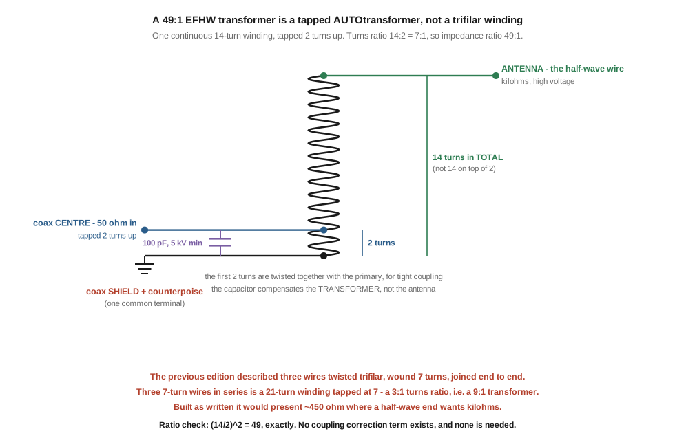
The lead figure shows what a 49:1 actually is. It is a single continuous winding of fourteen turns, tapped two turns up from the grounded end — an autotransformer, not three separate wires:
- Ground terminal: the start of the winding. The coax shield and the counterpoise both land here; they are one terminal, which is the physical expression of Vol 1’s point that the return current has to go somewhere.
- Coax centre: the tap, two turns up. This is the 50 Ω input.
- Antenna: the far end of the fourteenth turn. Kilohms, and at the legal limit, kilovolts.
- Compensation capacitor: across the primary, from tap to ground. 100 pF at 5 kV minimum.
The ratio check is the one this dive has had to make repeatedly: (14/2)² = 49, exactly, with no correction term. There is no “magnetic coupling” adjustment — that claim was live on this page and was removed in an earlier pass, and it is worth restating here because the arithmetic invites it: fourteen is the total, not fourteen on top of the two. Adding them to get sixteen and squaring 16/2 gives 64, which is a correct sum for a different transformer.
Two construction details that matter and that the schematic cannot show:
- The first two turns of the secondary are twisted together with the primary, so the primary is bifilar-coupled to the section it feeds. This is what makes the thing behave as a transmission-line transformer at the top of HF rather than as a plain autotransformer. The winding diagram this dive reproduces, by N4LQ, draws it this way, and its secondary is numbered 1 → 14 — corroborating the total-of-fourteen reading from a source independent of the arithmetic.
- The turn count is a band decision, the ratio is not. Vol 4 established this from measurement: 2:14, 3:21 and 5:35 are all 7:1 and all 49:1, and more primary turns means more magnetising inductance and less loss at the low end, at the cost of winding capacitance up high. VK3IL’s 200 Ω primary rule is what decides it — 3:21 or 3:24 for the low bands, 2:14 or 2:16 for the high ones.
The full transformer-designer treatment — mixes, winding topologies, why the compensation capacitor is a poor fit for low-leakage winding styles — is in the BALUNs and UNUNs dive, and is not duplicated here.
5.3 Building a 40 metre end-fed half-wave
The reference build is a 40 m end-fed half-wave covering 40, 20, 15 and 10 m. About two hours plus tuning.
5.3.1 Bill of materials
Table 1 — Bill of materials
| Part | Specification | Quantity |
|---|---|---|
| Antenna wire | #18 or #20 AWG copper-clad steel, or insulated stranded | ~68 ft, cut long |
| Counterpoise wire | same stock | ~7 ft |
| Transformer core | FT240-43 ferrite toroid — see the note below on core count | 1 or 2 |
| Winding wire | #16 to #18 enamelled magnet wire | ~2 m |
| Compensation capacitor | 100 pF, 5 kV minimum, ceramic or mica | 1 |
| Enclosure | weatherproof box, PVC or printed PETG | 1 |
| Coax connector | SO-239 or BNC chassis mount | 1 |
| End insulator | dog-bone, plastic or ceramic | 1 |
| Halyard | 1/8″ Dacron — not nylon, which stretches and degrades in UV | 10 m+ |
| Weatherproofing | self-amalgamating tape plus an outer vinyl wrap | 1 roll each |
⚠ Prices have been omitted deliberately. The previous edition quoted a per-part price list totalling about $64, none of it attributable to a dated source, and this program has previously shipped fabricated “verified” prices in a build section. §8 carries the figures that were verified against live vendor pages, and they are dated.
🔴 One core or two. The winding diagram this dive reproduces specifies “240-43, use min. of 2 cores” for a 49:1, while the previous edition’s table rated a single FT240-43 at 200 W SSB. Vol 4 settled which to believe: calculation and measurement agree that a single FT240-43 with a two-turn primary is a lossy transformer — around 1.4 to 2.3 dB, meaning a third to a half of your power heating the core. Build it with two cores unless you are staying at QRP levels. The single-core version works; it is simply not efficient, and §5 explains why that matters more than it sounds.
5.3.2 Procedure
- Wind the transformer. Fourteen turns of enamelled wire through the stacked cores, counting a turn each time the wire passes through the hole. Before you start, lay the primary wire alongside and twist it with the wire that will form the first two turns, so those two turns are bifilar. Bring out three connections: the start of the winding (ground), the tap at two turns (coax centre), and the end of turn fourteen (antenna).
- Fit the capacitor across the primary — tap to ground. Voltage rating is not optional here; this point sits at a voltage maximum and a junk-box ceramic disc will fail.
- Mount in the enclosure. Solder every joint; no twist connectors. Bring the antenna and counterpoise terminals out through the box on proper hardware, and remember Vol 1’s finding that the box and connector add several picofarads at a point where several picofarads matters.
- Cut the wire long. Vol 2 puts the practical starting length at
468/ffeet, which for 7.15 MHz is 65.5 ft — and the free-space half-wave there is 68.8 ft, so anyone quoting something between the two is quoting a partially-corrected figure. Cut 68 ft and expect to remove two feet or more. Cutting long is the whole strategy: removing wire is trivial, adding it is a splice. - Attach the counterpoise. About 7 ft, to the ground terminal, per Vol 1 and Vol 4’s 5–10 % rule for a complete radiator.
- Fit a common-mode choke at the transformer, not at the shack end. Vol 4 §7 is the reason it must be resistive rather than merely large.
- Deploy with the transformer end at a convenient height and the wire running out horizontally or as a shallow sloper. Vol 2 §8 is the height argument: what you get on 40 m is set by height in wavelengths, and a 10 m support makes the fundamental a near-vertical-incidence antenna.
- Weatherproof last, after the trimming in §4 is finished.
⚠ Two corrections to the previous edition’s procedure, both small and both irritating in the field. Its step 4 tells you to trim “1 % short of theoretical λ/2” and then gives that as 67 ft from a stated λ/2 of 67.6 ft — but the free-space half-wave at 7.15 MHz is 68.8 ft, and 1 % short of it is 68.1 ft, so neither the input nor the output of that sentence is right. And its tuning step says that if the resonance lands high, you should “start over”. You should not: Vol 2’s trim table says 1 % of length is 71 kHz on the fundamental, so a wire 200 kHz high is about 2.8 % short — roughly 1.9 ft, which is a splice and some tape, not a new antenna.
5.4 Cut and trim with a VNA
The instrument, not the SWR meter, because of everything in Vol 4 §5: a lossy transformer flatters an SWR reading, so a comfortable SWR is not evidence that the antenna is right.
Sweep the fundamental first. Look for the resonance — the point where reactance crosses zero — rather than for the SWR minimum. On a lossy system those are not quite the same point, and the reactance crossing is the one that tells you about the wire.
Trim from the far end, in decreasing steps. Shortening raises the frequency, at about 71 kHz per 1 % of length on 40 m. Take off 6 inches, re-sweep, and let the measured shift tell you the scale factor for your installation rather than trusting the model.
Then check the harmonic bands, and expect them to have moved further. This is the part builders find surprising and it is Vol 2 §2’s arithmetic: because the harmonics are integer multiples, a trim that moves 40 m by 71 kHz moves 10 m by 284 kHz. A wire optimised on the fundamental will not be optimised on the fourth harmonic, and no single length optimises all four. Choose which band you care about most and accept the rest.
Expect the harmonics to sit high in their bands. Vol 2 §5: end effect grows with harmonic number, so the resonances creep upward by a few percent. That is why the fundamental is cut toward the bottom of 40 m rather than mid-band.
5.4.1 What a good build actually looks like
Acceptance criteria, with the previous edition’s 6 m row removed because Vol 2 showed it was wrong:
Table 2 — Acceptance criteria, with the previous edition's 6 m row removed because [Vol 2](/random-wire-end-fed/vol-2/) showed it was wrong
| Band | Harmonic | Expect |
|---|---|---|
| 40 m | 1 | resonance in the lower half of the band, SWR under about 1.8:1 |
| 20 m | 2 | under about 2.5:1, resonance high in the band |
| 15 m | 3 | under about 2.8:1 |
| 10 m | 4 | under about 3:1, often near the top |
| 30 / 17 / 12 m | — | 4:1 and worse. This is correct behaviour, not a fault — Vol 2 §4 |
| 6 m | — | not a harmonic of this antenna. 5 × 7.10 = 35.5 MHz, which is not a band; 6 m sits at harmonic 7.04. If it loads up, that is a fortunate accident, not a design feature |
⚠ These SWR figures are inherited from the previous edition and no source was found for them. They are retained because their shape follows from Vol 2 §6 — a good match on the fundamental degrading with harmonic number as the feedpoint resistance walks away from the transformer’s 2450 Ω target — but they are representative, not a specification.
The diagnostic that is worth memorising: if the fundamental is right and the harmonics are wrong, suspect the transformer. If everything is wrong together, suspect the wire length or the counterpoise. And if everything is suspiciously perfect, suspect the transformer — §9.
5.5 Power: the limit is thermal, and the published ceiling is optimistic
The previous edition’s power section is titled “UNUN core saturation” and lists saturation symptoms. The failure mode is thermal. Modelled at 1000 W on 160 m, the flux density in these cores reaches about 0.076 T against roughly 350 mT saturation — “even operating at 1000 W on the 160 m band, the cores would not saturate.” At kilowatt levels the next limit is not saturation either but voltage breakdown, around 5 kV peak-to-peak at the 2450 Ω output.
This is the fifth place in this dive and its companion where a thermal or inductive limit has been described as saturation, after the BALUNs and UNUNs dive, Vol 3’s iron-powder core, the “what to avoid” advice in §8 below, and the flat-SWR myth in §9. It is the corpus’s most persistent single error.
⚠ And two of the previous edition’s stated saturation symptoms describe parts that do not exist: severe saturation, it says, “can melt the toroid’s plastic casing or the magnetic-coupling wax.” A ferrite toroid has no plastic casing and no wax. It is a bare ceramic body, sometimes with a thin conformal coating. What actually melts is the enclosure, the wire’s enamel, and any hot-melt adhesive holding the assembly together — which is a real failure and worth describing correctly, because it tells you where to look.
5.5.1 The Curie-temperature error
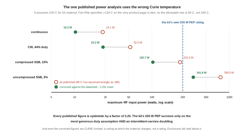
The only published end-to-end calculation of an EFHW transformer’s thermal limit analyses exactly the ARRL/HF-Kits kit — FT240-43, 2:14, 50 Ω to 2450 Ω, at 7.0 MHz. Its results are widely repeated. Its stated assumptions are 50 °C ambient, a Curie temperature of 230 °C, and therefore an allowable rise of 180 °C.
Fair-Rite specifies T_c > 130 °C for 43 material — on both the material datasheet and the individual product page the analysis cites as its own reference. The allowable rise is 80 °C, not 180 °C. Dissipation scales linearly with temperature rise, so every figure is optimistic by 180/80 = 2.25:
Table 3 — Fair-Rite specifies Tc > 130 °C for 43 material — on both the material datasheet and the individual product page the analysis cites as its own reference. The allowable rise is 80 °C, not 180 °C. Dissipation scales linearly with temperature rise, so every figure is optimistic by 180/80 = 2.25
| As published | Corrected | |
|---|---|---|
| Continuous | 23.1 W | 10.3 W |
| CW, 44 % duty | 52.5 W | 23.3 W |
| Compressed SSB, 10 % duty | 231 W | 103 W |
| Uncompressed SSB, 3 % duty | 769 W | 342 W |
| FT240-43 maximum dissipation | 6.17 W | 2.74 W |
Intermittent-service (ICAS) assumptions double all of them. The kit’s own 250 W PEP rating survives only on the most generous duty assumption combined with that doubling.
Two caveats belong with these numbers rather than after them. It is conceivable Fair-Rite revised the datasheet since the analysis was written, but the figure is >130 °C today on both pages, so the analysis and the datasheet disagree now. And even corrected, these are Curie-limited ceilings, not ratings — the temperature at which the material stops being a magnetic material. Permeability degrades, enamel softens and plastic boxes deform well below it. Treat the corrected column as an absolute ceiling and design a long way under it.
The measured cross-check from Vol 4 is the sanity anchor: at 21 W average, a good transformer put 2.00 W into its core on 80 m and rose 14.2 °C. Scale that and the corrected ceiling stops looking pessimistic — it looks about right.
⚠ One field report, from a customer review on a vendor’s own product page, is worth more than any of this arithmetic because it is first-hand and it cost the vendor something to publish: “I did have the transformer heat up while working FT8 at 150 watts on 80 meters. SWR went crazy, and I was not expecting that.” FT8 is essentially 100 % duty, on the band where loss is highest and rises with core temperature. That is the corrected thermal ceiling appearing in the field, exactly where the analysis says it should.
5.6 Rating by duty and by SWR
The previous edition gives a single wattage per core under a column headed “Continuous SSB”, which is close to a contradiction in terms — SSB’s entire thermal advantage is that it is not continuous. The trade does better, and its own published ratings are the model to copy.
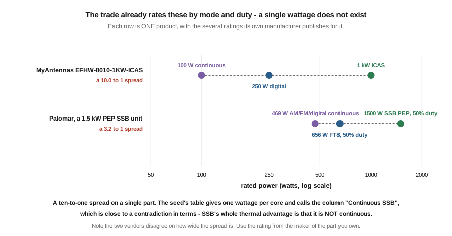
Table 4 — 6. Rating by duty and by SWR
| Product | The vendor’s own ratings | Spread |
|---|---|---|
| MyAntennas EFHW-8010-1KW-ICAS | 1 kW ICAS · 250 W digital modes · 100 W continuous | 10:1 |
| A Palomar 1.5 kW PEP SSB unit | 1500 W SSB PEP at 50 % duty · 656 W FT8 · 469 W AM/FM/digital continuous | 3.2:1 |
One part, several numbers. Note also that the two vendors disagree about how wide the spread should be, which is itself informative: use the rating published by the maker of the part you actually own, and treat a vendor who publishes only one number as having told you less than you need.
5.6.1 And derate again for SWR
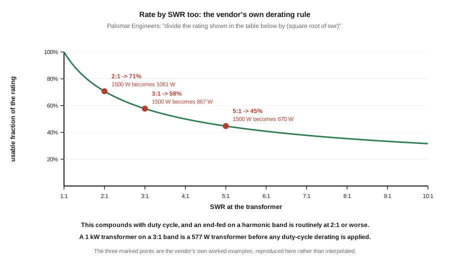
Palomar publishes an explicit rule: “divide the rating shown in the table below by (square root of swr).” Their worked examples, reproduced rather than interpolated:
Table 5 — Palomar publishes an explicit rule: "divide the rating shown in the table below by (square root of swr)." Their worked examples, reproduced rather than interpolated
| SWR | Usable fraction | A 1500 W rating becomes |
|---|---|---|
| 2:1 | 71 % | 1061 W |
| 3:1 | 58 % | 867 W |
| 5:1 | 45 % | 670 W |
This compounds with duty cycle, and it is not a corner case for this antenna. An end-fed half-wave on its harmonic bands routinely sits at 2:1 to 3:1 — Vol 2 §6 shows why that is normal rather than faulty. So a 1 kW-rated transformer on a 3:1 band is a 577 W transformer before any duty-cycle derating is applied at all, and a digital-modes operator should then apply the duty derating on top of that.
The practical rule this section replaces the seed’s table with: take the vendor’s rating for your actual mode, divide by the square root of the SWR you actually see on that band, and leave margin because the published numbers are ceilings. If that leaves you uncomfortable, the answer is more core — not for efficiency, which Vol 4 showed core size barely affects, but for the surface area to shed the heat.
5.7 Harmonics, and what Part 97 actually limits
An end-fed half-wave is resonant on every integer harmonic, which is the feature. It also presents a good match at those harmonics, which means that whatever harmonic energy the transmitter produces is radiated efficiently instead of being reflected. That is a real consideration, and the previous edition is right to raise it. Its numbers and its regulatory framing are both wrong.
5.7.1 The arithmetic
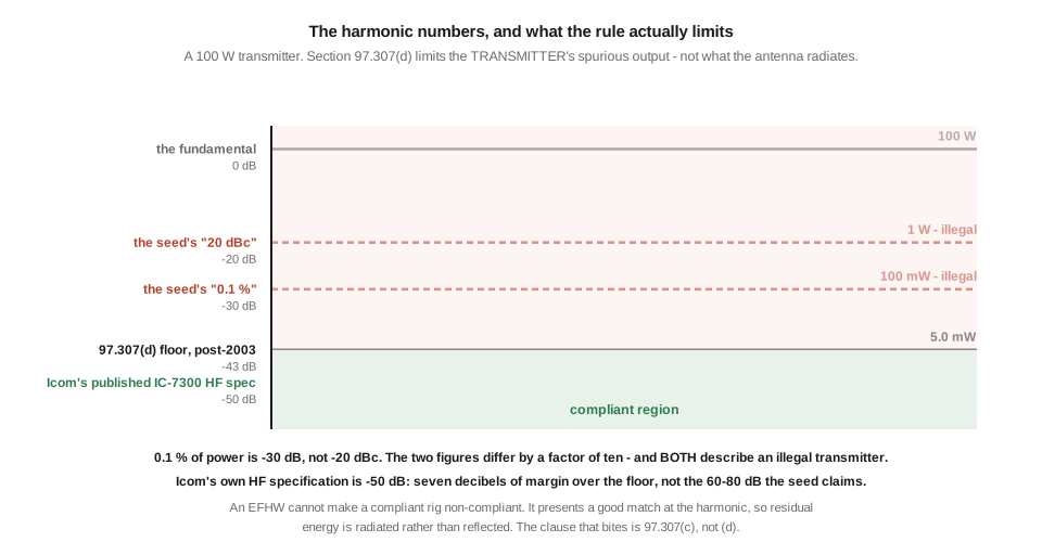
The chapter says a 100 W transmitter “can spit 0.1 % (20 dBc) of 2nd-harmonic signal into the air.” That is wrong twice:
- 0.1 % of power is −30 dB, not −20 dBc. −20 dB is 1 %. The two figures differ by a factor of ten and are presented as the same number.
- Either figure describes an illegal transmitter.
§97.307(d)requires spurious emissions below 30 MHz to be at least 43 dB below the fundamental for transmitters installed after 1 January 2003. At 43 dB down, 100 W yields 5.0 mW — not the 100 mW that 0.1 % implies, and certainly not the 1 W that 1 % implies.
5.7.2 The framing, which is the more important correction
§97.307(d) is a limit on the transmitter’s spurious output. It is not a limit on what the antenna radiates. An antenna does not create harmonic energy, and an end-fed half-wave cannot put a compliant transmitter out of compliance with (d). What it does is present a good match at the harmonic, so residual harmonic energy leaves as radiation rather than returning to the transmitter.
The obligation that actually engages in the antenna case is §97.307(c) — reduce spurious emissions to the greatest extent practicable, together with the general harmful-interference duty. That keeps the chapter’s practical advice intact (an end-fed makes a dirty transmitter matter more, and an in-line low-pass filter is the fix) while removing the false claim that the antenna is itself a compliance problem.
5.7.3 The transmitter cleanliness claim
The chapter says “modern Yaesu/Icom/Elecraft rigs have 60–80 dB of harmonic suppression at full power.”
Icom’s own published specification for the IC-7300 is “Less than –50 dB (HF bands).” That is 7 dB of margin over the regulatory floor, and 10 to 30 dB below the claim. Manufacturers specify minimums and typical units do better, but −50 dB is what the most popular modern HF transceiver’s maker actually publishes.
⚠ This point rests on one manufacturer’s specification. A second rig’s spec sheet was sought for this volume and not retrieved — the two obvious sources returned server errors — so the honest statement is that one major manufacturer publishes −50 dB on HF, not that the whole industry does. It is enough to retire “60–80 dB” as a general claim; it is not enough to assert a universal figure, and the gap is recorded in §10.
5.8 What to buy
⚠ Prices verified against live vendor pages on 31 July 2026. Everything not verified has been dropped rather than repeated, which is why this list is much shorter than the previous edition’s fourteen-row table — that table’s prices were undated and unattributed, and at least one of them conflicts with the vendor’s own current page.
Table 6 — 8. What to buy
| Product | Price | Rating as the vendor states it | Coverage |
|---|---|---|---|
| ARRL End-Fed Half-Wave Antenna Kit (built by HF Kits) | $79.95 | 250 W PEP | 40/20/15/10 m, ~66 ft |
| MyAntennas EFHW-8010-1KW-ICAS | $151.99–$179.99 | 1 kW ICAS, 250 W digital, 100 W continuous | 80–10 m |
| Palomar Bullet BAS-71X | $139.95 (list $159.95) | 500 W PEP | 71 ft, 80–6 m |
The realistic bracket is about $80 to $180 for a complete, purchasable end-fed half-wave. The previous edition’s “$30 kit to $300 engineered unit” reaches past both ends: bare 49:1 transformers exist below the range and multi-kilowatt units above it, but neither is what most buyers are choosing between.
🔴 One specific correction. The previous edition lists a “MyAntennas EFHW-8010-2K” at $400 that “handles 1.5 kW continuous.” The same manufacturer’s published rating for its 1 kW part is 100 W continuous. A claim of 1.5 kW continuous from this vendor is not consistent with how they rate their own products, and §5’s thermal arithmetic says it is not consistent with the physics either. Do not buy on that basis.
What to look for:
- A published rating that names a mode or a duty cycle. A single wattage with no conditions is not a specification, and §6 is the reason.
- A published core count, mix and turns ratio. The transformer is the antenna’s one active component; a vendor unwilling to say what is in the box has told you something.
- Two cores rather than one on anything claiming more than QRP power, per §3 and Vol 4.
What to avoid:
- A kilowatt claim on a small core in a pocket-sized box. The previous edition’s version of this warning says such units “will saturate under sustained transmit.” The advice is right and the mechanism is wrong: they overheat. Which matters practically, because the remedy for overheating is a bigger core or a lower duty cycle, while the remedy for saturation would be neither.
- “All nine bands, no tuner.” Vol 2 computed the harmonic series: the WARC bands are missed by 500 kHz, 318 kHz and 40 kHz respectively, and reaching them is a tuner story. Vendors do advertise it, and reviews on their own pages say otherwise.
5.9 Gotchas and myths, corrected
The previous edition’s list is mostly sound. These are the entries that changed.
“My SWR is 1.0:1 across all bands.” The chapter’s instinct is exactly right — this is bad news, not good — but it attributes it to “core saturation issues that are flattening the SWR by absorbing reflected power as heat.” It is loss, not saturation, and Vol 4 §5 quantifies it: with 2.3 dB of transformer loss, a genuinely 5:1 antenna reads 2.29:1, while about 41 % of your power becomes heat. The conclusion survives intact and is worth stating in its strongest form: a 50 Ω dummy load is perfectly flat on every band and radiates nothing at all.
“EFHWs don’t need a counterpoise.” Correct as far as it goes, but Vol 1 sharpened it: the antenna is not exempt from needing a return path, only from needing a radial field. And the improvement a counterpoise brings is not gain — a passive antenna is reciprocal — but a quieter receive noise floor and a station that stops misbehaving at power.
“More turns on the UNUN = better.” The chapter says the 2:14 standard is “well-optimized for HF.” Vol 4’s measurements say the optimum is band-dependent: 3:21 measured lower loss than 2:14 at 3 MHz, and VK3IL’s 200 Ω primary rule puts more turns on the low bands and fewer on the high ones. There is no single well-optimised answer.
“49:1 works on any wire length.” Correct, and Vol 3 generalises it: a fixed ratio into a variable load is fine only when you have arranged for the load to be near the ratio’s target, which is what cutting to a half-wave does and what a random wire deliberately does not.
“Counterpoise length must be λ/4.” Correct as stated — it is false — and Vol 4 §6 adds the distinction the chapter’s own selection table implies but never explains: 5–10 % applies to a complete radiator like an end-fed half-wave, while a random wire’s counterpoise is the other half of the antenna and needs to be a substantial fraction of it.
“The 49:1 UNUN is identical to a 49:1 BALUN.” Correct, and worth keeping. A balun is balanced-to-unbalanced; this is unbalanced-to-unbalanced. They are not interchangeable.
“EFHW is invisible to the FCC inspector.” Correct, and §7 supplies the sharper version: the antenna does not change what the transmitter emits, and the clause that engages is §97.307(c).
⚠ One item added. “A choke can only help.” Vol 4 §7 computed the counter-example: on a reactive common-mode path, any inductive choke reactance from zero up to about +j400 Ω leaves more current on the braid than fitting nothing at all. A choke must be high and resistive.
5.10 Where this dive ends
The end-fed wire family is now covered end to end. A resonant wire fed at a voltage maximum presents an impedance that is unbounded in the ideal model and installation-dependent in reality, so 2450 Ω is a convention and not a measurement. Every integer harmonic works, not the odd ones, which is why the coverage is a consecutive run of four bands — and why the WARC bands are structurally missed. A non-resonant wire’s length is not arbitrary, and four of the six lengths traditionally recommended collide with a half-wave multiple somewhere in an amateur band. A 9:1 re-centres an impedance range without narrowing it. The transformer costs real decibels, set by primary inductance rather than core size, and that loss hides itself by flattering the SWR reading. The counterpoise and the choke are one design decision. And the power ceiling is thermal, roughly half what the published analysis says, and properly expressed as a rating per mode and per SWR rather than as a number.
Two things this dive is owed, recorded rather than quietly dropped:
- Photographs. Every figure here is a hand-authored diagram. A build volume wants photographs of a real winding, a real enclosure and a real deployment, and those are Jeff’s to take. They are recorded in the dive’s
PHOTOS_NEEDEDlist rather than filled with stock imagery of someone else’s transformer. - Measurements this dive could not source. A per-band feedpoint sweep of one specific antenna, which would replace Vol 4 §2’s assembled spread; a measured set of harmonic resonances, which would replace Vol 2 §5’s over-predicting model; a verified feedpoint impedance for the end-fed long wire, which Vol 3 and Vol 4 both flag and neither can settle; and a second manufacturer’s harmonic-suppression specification, per §7. All four are bench or catalogue tasks rather than literature ones.
⚠ And one process note that belongs in the record. None of the five volumes in this dive has had an independent accuracy review — the author and the checker have been the same throughout. Self-review has been reliable on arithmetic and unreliable on attribution strength, which is the pattern this program has observed before. The figures were all generated from their formulas and passed through an XML bounds check that caught real layout faults, but none has been rendered by a browser. Both are pre-publish items.
5.11 Resources
- Fair-Rite Products — material datasheets and individual toroid product pages. The primary source for the Curie temperature in §5, and the reason that section exists; vendor and forum restatements of these figures are frequently wrong.
- N1FD (Blustine), Power Losses and Dissipation in Various Ferrite Devices — Part II — the thermal analysis §5 corrects. Its method is sound and its arithmetic is right; the input assumption is not.
- AF7NX, Engineering the EFHW 49:1 Transformer and Antenna and Performance of 49:1 Ferrite Core Transformers (Squash Practice) — the loss and flux-density measurements underpinning §5, and the calorimetric cross-check.
- Palomar Engineers, Choke and Transformer Power Rating and Derating Guide — the square-root-of-SWR rule and worked examples in §6, verified live 31 July 2026.
- MyAntennas product documentation — the ten-to-one duty-cycle spread in §6, and the field report quoted in §5, which is on the vendor’s own review page.
- 47 CFR §97.307 — the regulatory text in §7, read from the eCFR rather than from a summary.
- Icom IC-7300 published specifications — the −50 dB HF figure in §7.
- Sevick, Building and Using Baluns and Ununs — the standard reference for transmission-line transformer design behind §2.
- BALUNs and UNUNs, Vol 4 and Vol 5 — the transformer at designer depth, and the series-through S21 fixture that measures a choke properly.
- NanoVNA, Vol 3 and Vol 4 — calibration, and the sweep technique §4 depends on.
- Antenna tuners, Vol 1 — for the bands this antenna does not reach on its own.
Comments (0)