BALUNs & UNUNs · Volume 5
DIY Winding, Bench Verification, and Commercial Buys
Building the canonical five with real cores and real turn counts; the W2DU bead choke and the ferrite mix it actually uses; the series-through S21 fixture that measures choking impedance — replacing an SWR check that cannot see it at all; what a good sweep looks like and how saturation, overheating and a wrong Z₀ each appear differently on it; commercial options by tier; and the gotchas that catch first builds
5.1 About this volume
Four volumes of theory arrive here. This one builds the devices and — more importantly — verifies them, and the verification is where the seed material for this dive went most comprehensively wrong.
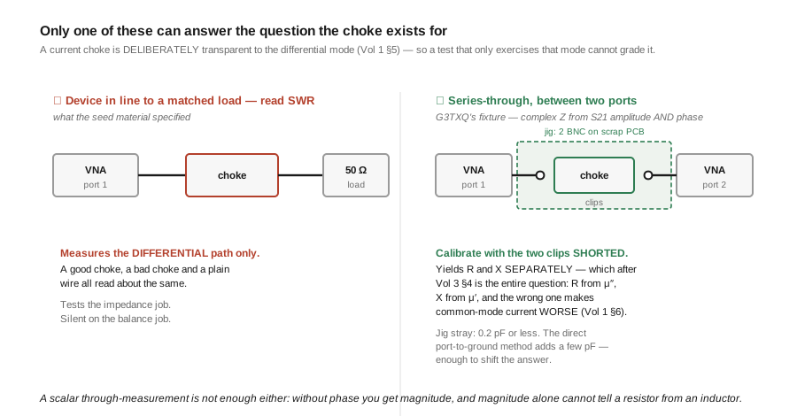
The seed’s test procedure was: connect the device’s input to a VNA port, hang a resistor of the appropriate value on the output, sweep, and look for low SWR. That measurement is not wrong so much as blind. It exercises the differential path only, and Vol 1 §5 established that a correct current balun is deliberately invisible to the differential mode. So a good choke, a bad choke, and a plain wire all read about the same. The seed’s fallback — “tape a small loop antenna near the BALUN’s coax shield and measure the coupling” — is not a procedure with a number at the end of it.
§8 replaces both with the method G3TXQ used to produce the measurements this dive has been citing throughout: the device in series between two ports, complex impedance recovered from S21 amplitude and phase. It is the only arrangement that yields R and X separately, which after Vol 3 §4 is the whole question.
A note on scope. The build sections give core designations, turn counts and Z₀ targets — the things that determine whether the device works, all of which trace back to a derivation earlier in the dive. They deliberately do not invent supplier part numbers or prices; §10 explains that decision rather than papering over it.
5.2 What actually limits a build
Before any BOM, the three limits worth designing against, each established earlier:
Turns set where the device works, not how well. Vol 3 §6: more turns moves the useful region down in frequency, and Vol 2 §9: more turns brings the high-frequency end down too. There is no turn count that is simply “better”. Every number below is a choice of where.
Z₀ must be the geometric mean, and only matters for transformers. Vol 2 §7. A 1:1 choke wound with the feed coax gets this right for free. A 4:1 does not, and this is the most commonly skipped step in a home-wound 4:1.
The power limit is thermal for a choke and magnetic for a high-ratio transformer. Vol 3 §8 and Vol 4 §11. They want different remedies — surface area and stacking versus a bigger core and more turns — so diagnosing which one you have matters before spending money.
5.3 DIY — the 1:1 current choke
The most useful thing in this volume, and the one that belongs at every coax-fed feedpoint in the hub.
Bill of materials. An FT240-size ferrite toroid in the mix chosen for your bands per Vol 3 §7 — mix 31 for 160/80/40 m, mix 43 for 40 m through 10 m; a length of the feed coax itself (RG-58 for modest power, RG-400 or RG-303 where more is wanted — G3TXQ notes RG400 substitutes for RG58 “with little change to the choke impedances”); a die-cast aluminium enclosure of the 1590B size class; an SO-239 (or N) chassis connector; two stainless studs for the antenna terminals; and self-amalgamating tape for the outdoor connection.
Construction.
- Wind the coax through the core. Pass it through the hole, around the outside, back through — that is one turn. Aim for 11–14 turns on a single core for mid-HF, fewer for a higher-frequency emphasis. Spread the turns evenly; leave a gap between the first and last turn rather than letting them touch, because that gap is what limits the winding’s end-to-end capacitance and therefore the high-frequency end.
- Do not cut the coax. This is the whole elegance of the 1:1: the coax passes through continuously, so
Z₀is right by construction (Vol 2 §7) and there are no joints in the signal path. If a build calls for cutting and reconnecting the coax, it is not this device. - Mount so the winding clears the enclosure walls by a couple of millimetres. Ferrite against aluminium is a mechanical risk — the core is brittle — and a tight fit traps heat, which §2 says is the limit.
- Weatherproof. Seal the seam and the connector. Water in the enclosure soaks the ferrite, and a wet core’s permeability is not the one you designed for.
Verification is §8. The number you want is Z_cm ≥ ~1 kΩ and predominantly resistive across every band you use (Vol 1 §7).
Scaling up. If the sweep shows the peak in the right place but the magnitude short, stack a second core rather than adding turns — Vol 3 §6: stacking multiplies A_e and leaves the frequency dependence alone, while turns move the peak.
5.4 DIY — the 4:1 Guanella
Two FT240-size cores in the same mix, and here the wire matters as much as the core.
The Z₀ requirement. Working 200 Ω → 50 Ω, each of the two lines needs Z₀ = √(50 × 200) = 100 Ω (Vol 2 §7). That is not 50 Ω coax. You need a two-wire line of about 100 Ω, which in practice means a bifilar pair of enamelled wire spaced by its own insulation — a modest twist, not a tight one. A tight twist raises the capacitance and drops Z₀ below where you want it; a loose one runs high. This is the step that separates a 4:1 that is flat across HF from one with a dip in it, and it is why “I wound it with the coax I had” produces the Z₀/R = 0.5 curve of Vol 2 §7.
Construction. Wind each core with a bifilar pair, 8–12 turns, matched between the two cores. Then connect them as Vol 2 §8 derives: inputs in parallel on the 50 Ω side, outputs in series on the 200 Ω side. Keep the two cores’ windings identical — an asymmetry between them shows up as exactly the current imbalance the current topology exists to prevent.
Verification. A 200 Ω non-inductive load on the output; the differential sweep should be flat, and a dip centred somewhere in HF is a Z₀ error, not a core problem (Vol 2 §7).
5.5 DIY — the 9:1 unun
An FT140-size core suffices for receive and low power; FT240 for a hundred watts and up. Mix per Vol 3 §7.
Construction. Three wires wound together — trifilar, 10–12 turns, lightly twisted — with the three windings connected in series so the taps give a 3:1 turns ratio and therefore 9:1 impedance. As a Guanella it would instead be three separate lines at Z₀ = √(50 × 450) = 150 Ω; the trifilar autotransformer is the common form and, since an unun has no balance to preserve, that trade is sound (Vol 2 §10).
And it is half an installation. Vol 4 §6: a 9:1 is a range-shifter, not a match. Budget for a tuner behind it, and for a separate 1:1 choke on the coax side, because an unun does nothing about common mode (Vol 4 §10).
5.6 DIY — the 49:1 EFHW transformer
The most-built device in modern amateur radio, and the one whose arithmetic Vol 4 §7 had to correct.
The winding, stated so it cannot be miscounted. A 2 : 14 transformer: primary 2 turns, secondary 14 turns in total. Turns ratio 14/2 = 7, impedance ratio 49. The 14 is not 14 more on top of the primary; adding them is the double-count that produced the seed’s phantom “magnetic coupling correction”. 3:21 and 5:35 are equally valid 7:1 windings — choose the absolute count for the core and the bandwidth you want (Vol 3 §6).
Core. FT240-size for a hundred watts; a larger core or a stack for legal-limit work, and note that here the limit is saturation on the lowest band rather than heating (Vol 4 §11) — so the remedy is a bigger core or more turns, not more surface area.
Construction.
- Twist the primary with the secondary’s first turns. The common published form bifilar-twists the 2 primary turns together with the first 2 turns of the secondary rather than merely being them, because Ruthroff’s coupling condition (Vol 2 §9) is what sets the high-frequency end.
- Wind the remaining secondary turns around the rest of the core, spread evenly.
- Connections. Coax centre to the primary; coax shield and the counterpoise to the cold end; the antenna wire from the secondary’s far end.
- The compensation capacitor — 100–150 pF, in a high-voltage part (mica or HV ceramic, a few kV; a small ceramic disc is not adequate at the high-impedance end of a kilowatt system). ⚠ Add it while watching a sweep, not on faith: its value resonates against your primary’s inductance, so a value copied from a design with a different winding is likely to be wrong (Vol 4 §8). And published designs disagree about where it connects — follow the one you are building.
- The choke is a second device. Vol 4 §10: a 1:1 current choke on the coax side of the unun. This is the step most cheap commercial EFHW assemblies omit.
5.7 The W2DU bead choke, and the mix it actually uses
The bead-string choke deserves its own section because it is the classic portable and in-line solution, and because the seed material got its material wrong in a way that matters.
What the seed said: “50–100 Mix-43 ferrite beads slid over the coax.”
What the design actually uses: #73-mix beads over small-diameter coax — the kits built to Maxwell’s design are described as shipping fifty #73 beads with a short length of RG-303 and a copy of his March 1983 article describing the choke.
⚠ A note on the strength of that citation, since this volume is correcting the seed and should not simply substitute a differently-sourced claim. Maxwell’s own article was not read directly in this pass, and the vendor pages carrying the kit descriptions refused automated retrieval. The mix-73-rather-than-43 correction rests on consistent secondary descriptions of the kits plus the independent physical argument below, which is why it is stated as what the design uses rather than as a quotation from Maxwell. The bead count and coax type should be confirmed against his article or a current vendor page before being relied on for a build.
Mix 73, not 43 — and the substitution is not cosmetic. From Vol 3 §5, Fair-Rite specifies mix 73 as “supplied only in small cores to suppress conducted EMI frequencies below 50 MHz”, with an initial permeability of 2500 — the highest of the set. That is precisely the profile wanted in a bead sliding over thin coax: the most permeability available in a small physical volume, aimed below 50 MHz. Mix 43 in the same bead geometry gives less.
And the reason it works as a choke rather than as an inductor is Vol 3 §4’s criterion exactly: the #73 assembly becomes increasingly resistive above about 3 MHz, which is what makes it insensitive to feedline length — a resistive choke cannot be cancelled by the common-mode path’s reactance (Vol 1 §6). The choice is the right one by the criterion this dive derived four volumes later — which is the strongest part of the evidence that the mix really is 73 and not 43, independent of any vendor description.
Two practical notes:
- The choke’s rating is the coax’s rating. Nothing is wound; the limit is what the RG-303 or equivalent will carry.
- A bead string is best at the upper HF end. Getting a few kΩ down at 80 m takes a long string, which is why the wound-toroid choke of §3 is the better low-band answer. This is the same trade Single-Band Dipoles Vol 2 describes.
⚠ Note also the name. As the vendors themselves acknowledge, “balun” is a misnomer here: it is a ferrite-loaded coaxial RF choke that happens to give the same result as a 1:1 current balun — which is Vol 4 §4’s point about the 1:1 restated by the people selling it.
5.8 Bench verification — the fixture that actually works
Here is the volume’s central correction.
Why the obvious measurement fails. Put the device between a VNA port and a matched load, sweep, and you measure the differential path. A correct current choke is designed to be transparent to that path (Vol 1 §5), so the measurement returns “fine” for a good choke, a bad choke, and a shorting link alike. It tells you about the impedance job and nothing about the balance job. Measuring the wrong quantity carefully is not verification.
Why measuring to ground also fails. The next instinct is to connect the choke from the port to ground and read its impedance directly. G3TXQ tried exactly that and rejected it, in his own words:
“My early attempts at choke impedance measurement used a Vector Impedance Analyser (AIM4170) with the choke directly connected from the measurement port to ground. However it’s not ideal: very high choke impedances are outside the range where the analyser can be expected to be accurate, and despite careful calibration to the measurement plane the analyser always added the equivalent of a few pF of parallel capacitance; this significantly shifts the self-resonant-frequency of higher-Q chokes such as those wound on Type 61 material or air-cored.”
A few picofarads of stray capacitance is enough to move the answer, because a good choke is a high-impedance, moderately-high-Q object.
The method that works is a series-through measurement of the attenuation the choke introduces:
“It turns out that more accurate results can be obtained by measuring the attenuation the choke introduces when placed between a signal source and a load.”
with the essential refinement that a scalar version of this is not enough:
“However this simple scalar measurement will not tell you anything about the choke’s complex impedance (its resistance and reactance), which as we have seen is vital for a complete understanding of how well it will perform.”
Hence two ports:
“Fortunately, a 2-port Vector Network Analyser can measure both the magnitude and the phase of the attenuation introduced by the choke, and that allows us to fully determine the choke’s complex impedance.”
The fixture, as he describes it: “a test jig comprising two BNC male connectors mounted on a small piece of PCB material; ‘crocodile clips’ soldered to the BNC centre pins allow the choke to be connected in line.” Calibration is with the two clips shorted together. Then “the choke is connected between the clips, and a VNA measurement scan made between the required frequencies. The resulting S21 Amplitude and Phase data is then transferred to a spreadsheet to calculate the choke’s complex impedance.” His jig “typically adds the equivalent of 0.2pF or less of parallel capacitance” — a twentieth of the stray the direct method contributed.
A NanoVNA is a two-port instrument and does this perfectly well; see NanoVNA Vol 4 for S21 technique and NanoVNA Vol 3 for why the shorted-clips calibration matters as much as the measurement.
5.9 Reading the sweep — and what each failure looks like
With R and X in hand, the four failure modes this dive has described become distinguishable — which is the practical payoff of the whole sequence.
Table 1 — 9. Reading the sweep — and what each failure looks like
| What the sweep shows | What it means | Fix |
|---|---|---|
Z_cm high but X > R on your bands | Wrong mix for the frequency — the core is still an inductor. This is the dangerous case: a reactive choke can increase common-mode current (Vol 1 §6) | A mix whose resistive region covers your bands (Vol 3 §7) |
Z_cm resistive but too low | Right mix, not enough of it | Stack cores (Vol 3 §6) — not more turns |
| Peak in the wrong place | Turn count | More turns moves it down, fewer up (Vol 3 §6) |
| Differential path shows a dip mid-band | Z₀ error in a transformer’s line | Rewind at the geometric mean (Vol 2 §7) |
| SWR shifts during a transmission, recovers between, worst on the lowest band | Core saturation — a high-ratio transformer problem | Bigger core, more turns, higher-saturation mix (Vol 4 §11) |
| Performance drifts over minutes, recovers slowly, band-independent | Overheating | Surface area, stacked cores, lower duty (Vol 3 §§8–9) |
The two rows in the middle of that table are the ones worth internalising, because they look identical on a magnitude-only plot and want opposite remedies.
5.10 Commercial buys
The DIY case is strong — a 1:1 choke is half an hour’s work from a core, a length of coax and a box — but there are good reasons to buy: weatherproofing done properly, legal-limit power ratings backed by someone’s testing, and a published performance curve.
What to look for, in priority order. Each of these is a question this dive has given you the means to ask:
- A published
Z_cmcurve withRandXshown separately. After §8 this is the single most informative thing a vendor can offer, and its presence is a strong honesty signal. A magnitude-only curve is much less useful; no curve at all means you are buying on reputation. - A stated core mix, or at least a stated band range. Vol 3 §7 — a device sold as covering “1.8–30 MHz” on one core is making a claim its material probably cannot support at both ends.
- Current topology, not voltage, for anything feeding a balanced antenna (Vol 2 §5).
- For an EFHW assembly: two cores. Vol 4 §10 — a single-core 49:1 solves the ratio and leaves the balance problem entirely. This is the most common shortcoming in the budget tier.
- Power ratings with stated conditions. A bare “1 kW PEP” without ambient, duty, enclosure or SWR is a marketing number, not a specification.
By tier, in terms of what you are actually paying for:
Table 2 — By tier, in terms of what you are actually paying for
| Tier | What you get | What to check |
|---|---|---|
| Budget | A wound core in a plastic box. Often works. | Core mix unstated; frequently a single core in an EFHW assembly; no published curve |
| Mid | Named topology, a stated power rating, decent weatherproofing, often a curve | That the curve shows R and X, and that an EFHW kit includes the choke |
| Premium | Tested ratings, high-power cores or stacks, published curves, serious enclosures | Mostly worth it for legal-limit and permanent installations |
| DIY | A third or less of mid-tier cost, and you choose the mix for your bands | Your own verification per §8 — which is the part the tiers above are really selling |
On specific products and prices, a deliberate omission. This pass did not verify vendor part numbers and prices against live pages, so it does not print any. That is not fastidiousness: the seed material for this dive quoted the same product at two different prices in two different sections, and a sibling dive in this hub shipped three fabricated “verified” prices before review caught them. A dated price list that is wrong is worse than a description of what to look for, because it reads as researched. The named families worth searching are Balun Designs, DX Engineering, MyAntennas, Palomar Engineers and Unadilla (who make the W2DU series to Maxwell’s design); check current pricing yourself, and apply the five questions above to whatever you find.
5.11 Gotchas and myths
- “The SWR is 1:1, so the balun is working.” SWR is a differential-mode measurement and a current balun is transparent to that mode. This is §8’s whole point, and it is the most common false confidence in the subject.
- “More choking impedance is always better.” Not if it is reactive. Vol 1 §6: a few hundred ohms of reactance can cancel against the common-mode path and quadruple the braid current. High and resistive.
- “The required impedance is ten times the load impedance.” G3TXQ tested rules of this form and found them “unsound” — the common-mode path is a property of the installation and the differential load does not appear in it (Vol 1 §7).
- “A balun and a common-mode choke are the same thing.” A 1:1 current balun and a choke, yes. A 49:1 unun and a choke, not remotely — they solve different problems and an end-fed antenna needs both (Vol 4 §10).
- “Ferrite mixes are identified by colour bands.” Colour coding is an iron-powder convention. Ferrite toroids are not colour-coded, and a painted “ferrite” core is probably not ferrite at all (Vol 3 §10).
- “Mix 43 is the 1.8–30 MHz workhorse.” It is a genuinely good mid-HF mix, and it gives up its low-band performance first. Fair-Rite specifies mix 31 from 1 MHz and 43 from 20 MHz (Vol 3 §7).
- “The 49:1 winding is 2 + 14 = 16 turns.” It is 2 : 14 — secondary 14 in total, ratio 7:1 (Vol 4 §7). 2 : 16 is a different, genuinely 64:1 transformer.
- “My balun is rated 1 kW PEP, so I can run 1 kW of RTTY.” PEP is a peak rating and the core’s limit is thermal. A constant-carrier mode is a different problem, and one to solve with a bigger core rather than a multiplier from a table (Vol 3 §9).
- “Bigger core is always better.” Bigger raises impedance and saturation headroom; it does not move the resistive region, which is set by the mix. A larger core in the wrong mix is a larger wrong choke.
- “I can wind a 4:1 with the coax I have.” Not well. A 4:1 wants
Z₀ = 100 Ωper line; 50 Ω coax puts a dip in the passband for no reason (Vol 2 §7). - “An unmarked core is probably 43, everyone uses 43.” Measure it (§Vol 3 §10) or keep it out of anything load-bearing.
5.12 Where this volume — and this dive — hands off
The dive’s own thread, in one line each: Vol 1 the common-mode problem and the resistive criterion · Vol 2 the topologies and the Z₀ condition · Vol 3 the material, from complex permeability · Vol 4 the ratios and the corrected EFHW arithmetic · this volume, building and proving one.
Outward to the antennas whose feedpoints this dive serves: Single-Band Dipoles (1:1 at 73 Ω) · Multi-Band Dipoles (4:1, OCFD and folded) · Random Wire & End-Fed Antennas (9:1 and 49:1) · Fixed Vertical Monopoles and Portable & Mobile Monopoles (chokes on unbalanced feeds) · Yagi-Uda Vol 3 (matching inside the array) · Transmitting Loops.
For measurement: NanoVNA Vol 3 for calibration discipline and NanoVNA Vol 4 for S-parameter technique. For what a fixed ratio cannot reach: Antenna Tuners. For the feedline and grounding context: Theory & Practice.
Photographs still owed for this dive — including two that are measurements of a real build and are deliberately left empty rather than filled with a borrowed curve — are listed in the dive’s PHOTOS_NEEDED note.
5.13 Resources
- Hunt, S. E. (G3TXQ), “Common-mode chokes.” The measurement method quoted in §8 verbatim — the rejection of the direct port-to-ground approach, the series-through S21 fixture, the shorted-clips calibration, and the 0.2 pF figure — plus his spreadsheet for deriving complex
Zfrom S21, and the per-mix charts Vol 3 §6 draws on. © G3TXQ; reachable through the Internet Archive since the site’s certificate lapsed. - Maxwell, W. (W2DU), the March 1983 article describing the bead choke balun, and Reflections. The origin of the design in §7. ⚠ Not read directly in this pass — the article was not reached and the vendor pages carrying the kit descriptions refused automated retrieval. §7’s correction of the seed’s “Mix-43 beads” therefore rests on consistent secondary descriptions of the kits plus the independent argument from mix 73’s published characteristics, and says so in place.
- Brown, J. (K9YC), “Coaxial Transmitting Chokes.” The other widely-used modern body of choke measurement and practice, complementary to G3TXQ’s.
- Sevick, J. (W2FMI), Understanding, Building, and Using Baluns and Ununs: Theory and Practical Designs for the Experimenter and Transmission Line Transformers. The standard construction references for every ratio here.
- Ruthroff, C. L., “Some Broad-Band Transformers”, Proc. IRE, August 1959, pp. 1337–1342. The coupling condition behind §6’s bifilar primary.
- Fair-Rite material data sheets. Mix selection per Vol 3 §5; the mix-73 characterisation quoted in §7.
Comments (0)